FIRST-ORDER POTENTIAL-BASED PANEL METHODS
As an example of the more recent first-order panel methods, some of the features are discussed, following the six steps used for the previous computational methods. It is recommended at this phase that the students use one of the available panel codes along with its graphical pre – and postprocessor. It is useful to become familiar first with the preprocessor and the grid-generation
process, through homework assignments, and only later devote more time to the aerodynamic results. In the following discussion, some of the features of a first-order method (e. g., VSAERO,1210,1211 and PMARC,12 14) are described.
Choice of singularity elements. The basic panel element used in this method has a constant strength source or doublet, and the surface is also planar (but doublet panels that are equivalent to a vortex ring can be twisted). Following the formulation of Section 9.4, the Dirichlet boundary condition on a thick body can be reduced to the form of Eq. (9.23), which states that the perturbation potential inside the body is zero:
N Nw N
2 QM* + 2 + 2 Bkak = 0 (12.29)
*=i i=i *=i
This equation will be evaluated for each collocation point inside the body and the influence coefficients Ck, Ci of the body and wake doublets and Bk of the sources are calculated by the formulas of Section 10.4.
Both the VSAERO1210,12 11 and PMARC12 14 computer programs allow additional modeling of zero-thickness surfaces by vortex-lattice grids that are treated as shown in Section 12.2. On these surfaces the zero normal velocity boundary condition is used, which results in a similar set of equations on the collocation points of panel i:
2 Cipk + 2 C?>, + 2 B*kok = —Qoo • n, (12.30)
k=l /=1 *=1
The Bk, Ck induced velocity coefficients are given, too, in Section 10.4.
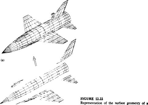
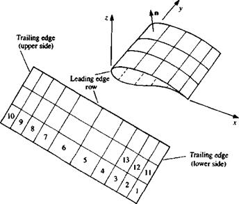
Discretization and grid generation. In this phase the shape of the body is divided into surface panel elements as shown in Fig. 12.22. It is useful to have a graphic representation of the grid so that possible input errors such as gaps between the panels and misplaced corner points can be corrected. The grid is usually constructed of rectangular subgrids (patches) and some of the patches forming the model of Fig. 12.22 are shown as well. Note that triangular panels, as in the nose cone area, are actually rectangular panels with two coinciding comers. At this phase the panel comer points, collocation points (which may be on the surface or slightly inside the body), and the outward normal vectors n*. are identified. Also, the counter к for each panel is assigned and a typical example of generating a wing grid and its unfolded patch is shown in Fig. 12.23.
![]()
![]() Influence coeflicifents. In this phase the boundary conditions of Eq. (12.29) (or (12.30)) are evaluated and for this example we shall use only the Dirichlet boundary condition. As was noted earlier, Eq. (12.29) is not unique and the combination of sources and doublets must be selected. For example, fixing the source strengths as
Influence coeflicifents. In this phase the boundary conditions of Eq. (12.29) (or (12.30)) are evaluated and for this example we shall use only the Dirichlet boundary condition. As was noted earlier, Eq. (12.29) is not unique and the combination of sources and doublets must be selected. For example, fixing the source strengths as
|
generic airplane by subarrays (patches): (a) (b) complete model; (b) separate patches. |
|
FIGURE 12.23 Method of storing the grid information on a wing patch (and identifying the wing’s outer surface). |
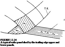
Wake made of constant-strength doublets
 will result in a unique set of equations with the doublet strengths as the unknowns. The above selection of the source strength is based on the results of Section 4.4 and includes most of the normal velocity component required for the zero normal flow boundary condition (in the nonlifting case). Consequently, the unknown fjk strengths will be smaller.
So, at this point, the potential at the collocation point of each panel (inside the body) is influenced by all the N other panels and Eq. (12.29) can be derived. Now, let us consider a wake panel that is shed by an upper panel with a counter / and a lower panel with a counter m, as shown in Fig. 12.24. Equation (12.29) for the first collocation point can be derived as:
Сц/fi H—– 1- СиЦі H– 1- Clmpm H—- 1- CXNpN + 2 Cipnp + 2 Blkok – 0
(12.32)
The influence of this particular wake panel at point 1, when singled out from
![]() (12.33)
(12.33)
where the counter p scans the wake panels. But this second summation of the wake influences in Eq. (12.29) does not contain additional unknown values of p. Therefore, the results of this second summation can be resubstituted into the equation, using the results of the Kutta condition (Eq. (12.33)). In the particular case of Fig. 12.24, the equation for the first point becomes
CnPi + ■ ■ • + (Cu + Cp)pi + • • • + (Clm — Clp)pm
+ • • • + CXNpN + 2 BXkok = 0
Consequently, this equation can be simplified to a form
![]()
![]()
![]() (12.34)
(12.34)
|
<*11> <*12> ■ a21> a22> ■ |
|
• > • . <*2IV |
|
1<*V1> <*N2, ■ |
 |
where Alk = Clk if no wake is shed from this panel and Alk = Clk ± Clp if it is shedding a wake panel. This equation now has the form
which is a set of N linear equations for the N unknown цк (ak is known from Eq. (12.31)). Also, note that akk = 1/2, except when the panel is at the trailing edge.
Establish RHS. The right-hand-side matrix multiplication can be carried out since the strengths of the sources are known. This procedure establishes the RHS vector and Eq. (12.35) reduces to the form:
|
<*ЛГ1, am, ■ |
|
aNN / A*IV |
![]()
 <*11, <*12, • • •, <*ілД /И 1 <*21> <*22, • • • , <*2N I / /*2
Solution of linear equations. The above matrix is full and has a nonzero diagonal, and a stable numerical solution is possible. Usually when the number of panels is low (e. g., less than 500) a direct solver can be used. However, as the number of panels increases (up to 10000 recently), iterative solvers are used so that only one row of the matrix occupies the computer memory during the solution.
Computation of velocities, pressures, and loads. One of the advantages of the velocity potential formulation is that the computation of the surface velocity components and pressures is determinable by the local properties of the solution (velocity potential in this case). The perturbation velocity components on the surface of a panel can be obtained by Eqs. (9.26), in the tangential directions,
and in the normal direction,
qn = 0 (12.37a)
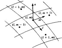
where /, m are the local tangential coordinates (see Fig. 12.25). For example,
FIGURE 12.25
 Nomenclature used for the differentiation of the velocity potential for local tangential velocity calculations.
the perturbation velocity component in the / direction can be formulated (e. g., by using central differences) as
qi = Y£l(t*i+- 4i-) (12.38)
where Дl is the panel length in the / direction. In most cases the panels do not have equal sizes and instead of this simple formula a more elaborate one can be used (sometimes only the term Д/ is modified). The total velocity at collocation point к is the sum of the free-stream plus the perturbation velocity
Qk = (2»,, G~m, Qoojk + (чь qm, qn)k (12.39)
where lk, mk, nk are the local panel coordinate directions (shown in Fig. 12.25) and of course the normal velocity component is zero. The pressure coefficient can now be computed for each panel using Eq. (4.53):
Срк = 1~Ш (12’40)
The contribution of this element to the aerodynamic loads AF*. is
AFk = – CPk(bQl)ASknk (12.41)
In many situations off-body velocity field information is required too. This type of calculation can be done by using the velocity influence formulas of Chapter 10 (and the strengths a and ц are known at this point).


