HIGHER-ORDER PANEL METHODS
The mathematical principle behind these methods is similar to that of the low-order methods, but the complexity of the element in terms of its geometry and singularity distribution is increased. The boundary conditions to be solved are still Eq. (12.29) (Dirichlet) and Eq. (12.30) (Neumann) or a combination of both (that is, on some panels the Neumann and on the other panels the Dirichlet condition will be used—but not both conditions on the same panel).
The influence coefficients are more complex and they depend on more than one singularity parameter (only one such a parameter was required for a constant-strength source or doublet element). In the following section a brief description of such a method is presented and more details on one of these methods (PAN AIR) is provided in Refs. 12.8 and 12.9.
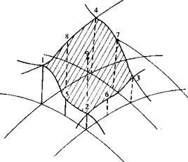
Choice of singularity elements. Using a first-order source and second-order doublet distribution as described in Section 10.5 allows us to determine the influence of each panel in terms of its values at its nine points (as shown in Fig. 12.26). The surface is divided into five subelements and the relative location of these points is shown in Fig. 10.27, too. The influence of the panel’s subelements can be summarized as:
ДФ = Fs(ou o2, ст3, o4, ct9) =fs(oQ, ox, Oy) (12.42)
Д(u, v, w) = Gs(ou o2, o3, o4, ct9) = gs(an, ox, oy) (12.43) for the first-order source element and
ДФ = Fd(jUi, fi2, Fi, Fa, Fs, Ft,, Fi, F*, F9) = fD(Fo, Fx, Fy, Fxx, Fxy, Fyy)
(12.44)
Д(и, v, w) = GD(plt F2, Fs, Fa, Fs, Fe, Fi, Fs, F9)
= go(Fo, Fx, Fy, Fxx, Fxy, Fyy) (12.45)
for the second-order doublet. The subscript 1 through 9 denotes the strength of the singularity distribution at this point according to the sequence in Fig.
12.26. Note that for a source five unknowns are used, but by assuming a linear strength distribution this can be reduced by algebraic manipulations to three (e. g., fs = a0 + axx + oyy). Similarly, by assuming a parabolic distribution for the doublet strength the number of unknowns is reduced to six per panel (e. g., gn = Fo + FxX + Fy У + FxyXy + FxxX2 + juyyy2).
 FIGURE 12.26
Typical points used to evaluate the influence of a higher-order singularity distribution.
Discretization and grid generation. The grid-generation procedure is similar to the procedure described for the zero-order method, but now all nine nodal points are stored in the memory. Also, gaps in the geometry are not allowed since a continuous geometry is assumed.
Influence coefficients. Again we shall follow the case where the strength of the source (for thick bodies) is set by Eq. (12.31):
ok ^ • Q x
The Dirichlet boundary condition can then be reduced to the form
6N Nw 3 N
2 Скцк + 2 CM + 2 вкак = 0 (12.46)
= 1 t= k = 1
or if the Neumann condition is used then on the /th collocation point
6N Nw 3 N
2 Ctlik + 2 Cl to + 2 В*кок = Q« • n, (12.47)
*=і /=i *=i
In principle, for N panels we have 6N unknown doublets, but by matching the magnitudes (or slopes) of the neighbor panels, 5N very simple additional equations can be obtained (see, for example, the two-dimensional case as in Section 11.6.1). These neighbor panel relations are resubstituted into Eq. (12.46) or Eq. (12.47) such that for N panels N linear algebraic equations must be solved. Also, as before, the wake doublets ju, do not contain any new unknowns and based on the corresponding doublet values of the wake shedding panels the wake influence can be substituted into the Ck, Ck coefficients. Thus for each panel i,
2 AikPk = – 2 Bikak (12.48)
*=і *=i
where the collocation point counter і = 1 —> N.
Establish RHS. The right-hand side of this equation includes the known source strengths (for the Dirichlet boundary condition) and the free-stream component normal to the surface (for the Neumann boundary condition case) and can be computed. The additional 2N equations for the source cornerpoint values are obtained by matching the source strength at the panel edges.
Solution of linear equations. Same as for low-order methods.
Computation of velocities and pressures. The local tangential velocity is calculated by using Eq. (12.37), but since at each panel there are nine values of fi a finer arithmetic scheme is used for calculating the local gradients of the velocity potential. Once the velocity components are found the local pressure coefficient and the aerodynamic loads are found by using Eqs. (12.40) and (12.41).
More details on such higher-order panel codes can be found in Refs. 9.3 or 12.9.


