Range—Payload and Endurance-Payload Relations
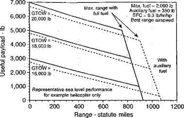
Range-payload and endurance-payload curves provide information of the effects of aircraft range and endurance when trading off payload for fuel. The specific mission for the aircraft must be defined, although most flight plans will involve a flight from point A to point B, as shown in Fig. 5.19. As previously explained, the engine characteristics must be taken into account to determine both the maximum endurance and maximum range. Fuel flow curves must be derived versus indicated airspeed and gross weight, and these depend on whether the helicopter is powered by reciprocating or turboshaft engines. Generally, the fuel flow curves versus airspeed (at a given density altitude) are fairly flat and so this alternative form of defining the performance curves closely follows the shapes of the power curves. McCormick (1995) lays down the basic range analysis for an aircraft, which can be adapted for the helicopter. The fuel bum, Wf, with respect to distance, R, will be
![]() dWF P x (SFC)
dWF P x (SFC)
dR V

where SFC is the specific fuel consumption of the engine(s). The power required, P, varies with gross weight and density altitude and, as already shown, the SFC depends on power and density altitude. Because the weight decreases as fuel is burned, Eq. 5.77 must be integrated numerically to find the range. Fuel burned during takeoff, climb, and descent is factored into the calculation, along with a mandated fuel reserve in minutes of flying time. However, because the fuel weight is normally a small fraction of the total gross weight of the helicopter (usually, but not always) then Eq. 5.62 can be evaluated fairly accurately at the point in the cruise where the aircraft weight is equal to the initial gross weight (gross takeoff weight, Wgtow) less half the initial fuel weight, that is, at the point where W = W’ = Wgtow — Wp/2, where Wf is the initial fuel weight. In this case the range, R, of the helicopter when cruising at speed V is given by
Range
Figure 5.19 A representative mission profile for a helicopter.
![]()
|
|
 |
|
 |
|
|
|
|
![]()
|

will be obtained at the speed for minimum power when Preq = Pait – Because this condition is approached asymptotically, the altitude at which this occurs can be determined by setting the rate of climb Vc arbitrarily to the low value of 1 fts-1 (0.3 ms-1) and solving Eq. 5.80 for the density altitude at which this condition is reached. This is called the service ceiling.
РаспНс cbnu/inrr tbp срп/Ірр рріїїгш qc q fimpfiAn nf fniP оігєпррН fnr РУОГППІР Ьр1І_
XVWUIXXI. L> U11V vt nig 111V UV1 T 1VV wiling UJ «X lUUWllVll vi VlUV Ull 1V1 L11V v/vuinpiv 11V11
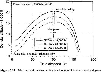
copter at different gross weights are given for standard atmospheric conditions in Fig. 5.21. This type of plot is often referred to as an operational flight envelope – see Fig. 6.38 for general operational flight envelopes of several rotorcraft configurations. It is apparent that the ceiling curves mimic the excess power available or maximum rate of climb curves, as would be expected. The ceiling that the helicopter can reach may be further qualified by specifying in ground effect (IGE) or out of ground effect (OGE) conditions – see Section 5.8. This is because operations IGE will reduce power required and so can help to augment the operational ceiling, a useful behavior when operating out of high altitude or mountainous terrain. However, the useful flight envelope may be further restricted by structural limitations that must be clearly defined to avoid inadvertent operations that may overstress the rotor – see Stepniewski & Keys (1984).


