. Pitching Moment and Related Issues
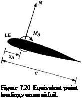
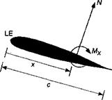
Because the pitching moment can be sensitive to small changes in the chordwise pressure distribution, its variation with AoA can be difficult to compute accurately. It may be estimated experimentally by direct measurement from a balance or by the integration of chordwise pressure about some reference point, as described previously. In either case, the pitching moment coefficient depends on the reference point chosen. For helicopter work, the 1 /4-chord point is normally used. Converting from one reference point to another uses the rules of statics. For example, assume the normal force and pitching moment are known at a point a distance xa from the leading edge of the airfoil and it is desired to find the pitching moment about another point, say at a distance x behind the leading edge (see Fig. 7.20). Taking moments about the airfoil leading edge in each case gives
 |
 |
Mx = Ma + N(x – xa). (7.57)
Converting to coefficient form by dividing by |poo V^c2 gives
![]() Cmx — Cn ( X Xq^ .
Cmx — Cn ( X Xq^ .
As an example, if the known pitching moment is about the leading edge, CmLE, then xa = 0 and the above equation becomes
![]() Сщх — CW££ -f xCn
Сщх — CW££ -f xCn
![]() Л, єfqdynamic Сєнієг
Л, єfqdynamic Сєнієг
There is one special point on an airfoil for which it is found that Cm is constant and independent of the AoA. This point is called the aerodynamic center. For angles of attack up to a few degrees below the stalling angle it is a fixed point on the chord and is relatively close to 1/4-chord. For a flat-plate airfoil in inviscid, incompressible flow, the aerodynamic center is theoretically on the 1 /4-chord axis. However, the thickness of the airfoil and viscous effects because of the development of a boundary layer usually cause the aerodynamic center to move a few percentages further forward or aft of the 1 /4-chord.
The aerodynamic center on an airfoil can be found with a knowledge of the normal force coefficient and the moment coefficient about any other known point. If the aerodynamic center is assumed to lie at a distance xac behind the leading edge, then
Cm. = cm„ + С» (j – ^f) = cm„ + C„ (xa – xac). (7.60)
Differentiating the above equation with respect to Cn gives
By definition, the aerodynamic center is that point about which the moment is independent of C„ and so the first term on the right hand side is zero. Therefore,
We can obtain dCma/dCn by using the result
![]() dP^wia dCfna dot
dP^wia dCfna dot
dCn da dCn
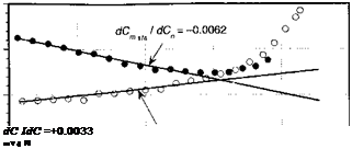
or if Cma is plotted versus Cn and the slope of the best straight line is found, then the aerodynamic center can be determined by using Eq. 7.62.
Representative results are shown in Fig. 7.21. In the attached flow regime, the data lie on a straight line, the slope of which gives the offset of the aerodynamic center from the 1/4-chord axis. For the SC1095 airfoil at this Mach number and Reynolds number, the aerodynamic center is located at approximately 25.6% chord, and for the SC1095-R8 the aerodynamic center is at 24.7% chord.
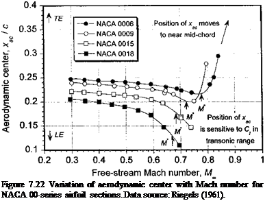
The effects of compressibility tend to move the aerodynamic center further aft of the 1 /4-chord, and for supersonic flow the aerodynamic center is situated near 50% chord. The measured behavior of the NACA 00-series airfoils is shown in Fig. 7.22, where it is apparent that the aerodynamic center initially tends to drift slightly forward with increasing Mach number. The explanation for this behavior lies in the effects of the pressure distribution on the developing boundary layer. Higher Mach numbers tend to form a pressure distribution
0


![]() 5 -0.01
5 -0.01
є
0
0 -0.02
о
CD
8 – о. оз
-и
С
0)
J -0.04
 -0.05
-0.05
-0.5 0 0.5 1 1.5 2
Normal force coefficient, C
’ n
Figure 7.21 Variation of C„,l/4 with C„ for SC1095 and SC1095-R8 airfoils at = 0.3.
Data source: Leishman (1996).
 |
that resembles one about an airfoil with a higher thickness ratio. Thin airfoils, such as the NACA 0006, tend to have an aerodynamic center that remains close to the theoretical flat-plate value of 1 /4-chord. Also, because of the higher critical Mach number of thin sections, the onset of shock waves is delayed and so the aft movement of the aerodynamic center occurs at relatively higher subsonic Mach numbers. When shock waves do occur (see Fig. 7.9), the movement of the aerodynamic center is dictated by the relative position of the upper and lower surface shock waves. Because these positions will be a function of both airfoil shape and AoA, a simple generalization of the aerodynamic center position in the transonic regime is usually not possible.


