Effect of Airfoil Shape on Dynamic Stall
McCroskey et al. (1980, 1982) have studied systematically the effects of airfoil shape on the dynamic stall characteristics of several different types of airfoils. Some of these airfoils are unsuitable for use on helicopters, but the results serve to bracket the effect of airfoil shape on the problem, albeit only at relatively low Mach numbers. Wilby (1984, 1996, 1998) reports another study of airfoil shape on the dynamic stall problem and over a much wider range of Mach numbers, including transonic flow. This author presents a tantalizing glimpse of a wealth of information on the dynamic stall problem; however, very little of these data have been formally published in the open literature. The datum airfoil used by McCroskey et al. (1980, 1982) was the ubiquitous NACA 0012, and results are summarized here for two other airfoils that are representative of modem rotor airfoils used on current production helicopters, namely the HH-02 airfoil (used on the AH-64 Apache) and the SC 1095 airfoil (used on the UH-60 Blackhawk). These are both cambered airfoils with approximately 9.5% thickness to chord ratios and can be considered
leading edge camber than the SC1095, and it has the distinction of a large trailing-edge tab (see Fig. 7.24).
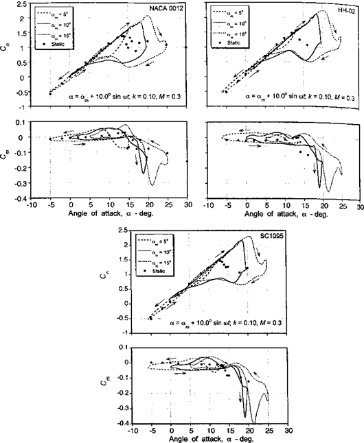
Some results showing the effects of airfoil shape on the dynamic stall airloads are summarized in Fig. 9.15, which shows the normal force and pitching moment coefficients for stall onset conditions through deep dynamic stall. In each case, the results are compared to the static airloads for that airfoil. The experimental data shown are for a free-stream Mach number of 0.3, which is the highest Mach number that was tested. At the lowest mean AoA of 5°, the maximum AoA becomes just large enough to initiate some minor leading edge separation, as evidenced by the distortion in the nominally elliptical hysteresis loops near
![]()

the maximum AoA. All three airfoils exhibit a significant increase in maximum lift over the static values. It is clear, however, that the HH-02 and SC 1095 airfoils maintain attached flow to a slightly higher AoA, with correspondingly higher values of Cn, and, thereby, exhibit a slightly superior lifting performance to the NACA 0012. This is consistent with the static behavior of these types of airfoils (see also Section 7.9). Therefore, it can be concluded that
airfoils designed for high static lift capability should also exhibit a higher AoA capability before stall when operated under dynamic conditions.
The forces and pitching moments for a case of moderately strong dynamic stall, which occurs for am = 10°, are also shown in Fig. 9.15. Under these conditions, relatively strong leading edge vortex shedding is initiated and the characteristic lift overshoots and strong nose-down pitching moment behavior of dynamic stall are intensified. Considerable hysteresis in the lift and pitching moment behavior is also present for these conditions. All three airfoils exhibit a qualitatively similar type of behavior, although it is apparent that there are measurable quantitative differences. The NACA 0012 exhibits moment stall at a lower AoA to either the HH-02 or the SC1095 airfoils, although the lift stall occurs at approximately the same AoA for all three airfoils. Both the NACA 0012 and the SC1095 airfoils exhibit a well-rounded moment break at the onset of dynamic stall in comparison to the HH-02, which has a very abrupt moment break. This suggests that some trailing edge flow separation is still present on the NACA 0012 and SC1095 airfoils prior to the onset of leading edge separation and dynamic stall. This also suggests that to some extent the static stall behavior of the airfoil is actually carried over into the dynamic stall regime. Both the HH-02 and SC 1095 airfoils exhibit a slightly greater maximum dynamic lift over the NACA 0012. Again, these static lift gains appear to be carried over somewhat into the dynamic regime. However, the NACA 0012 clearly exhibits a smaller peak value of (nose-down) pitching moment compared to the other two airfoils. This suggests a weaker shed leading edge vortex for the NACA 0012 airfoil.
As discussed in Chapter 7, the traditional approach in designing helicopter rotor airfoils is to maximize the quasi-steady lift and minimize the pitching moment. Little emphasis is usually placed on the consequences of the unsteady behavior of the airfoil. Figure 9.15 reinforces this point, where the oscillatory lift and pitching moment for a mean AoA of 15° indicate strong leading edge vortex shedding, producing significant increments in normal force and pitching moment coefficients. As for a mean AoA of 10°, all three airfoils exhibit a qualitatively similar type of dynamic stall behavior, with both the HH-02 and the SC 1095 airfoils exhibiting increased values of maximum dynamic lift over the NACA 0012. (It should also be noted that for each airfoil there is perhaps evidence of secondary vortex shedding near the maximum AoA, which manifest as smaller secondary peaks in the normal force and pitching moment.) It is significant that while under static conditions the SC 1095 exhibits a gain in maximum Cn of about 0.1 over the HH-02 airfoil, under these particular dynamic conditions there is almost no difference in maximum Cn between these two airfoils. This indicates that, whereas the maximum lift coefficient may be a useful measure of airfoil performance under static conditions, this does not necessarily appear to be an indication of the dynamic lift capability of the airfoil. Also, although the HH-02 and the SC 1095 airfoils give approximately the same value of maximum dynamic lift, the maximum nose-down pitching moment is clearly greater for the SC 1095. This is despite the fact that the HH-02 has a higher zero-lift pitching moment under quasi-steady conditions. Therefore, like the lift coefficient, the design of airfoils for low static pitching moments does not necessarily guarantee that low dynamic pitching moments will also be produced.


