Variation of Induced Velocity with Axial Distance
 |
 |
In subsequent material the variation of the induced velocity with axial distance from the propeller disk plane is needed. This variation can be
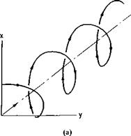
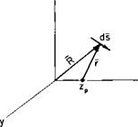
Fig. 4-13. Geometry of a helical vortex.
found approximately by calculating the axial velocity induced along the axis of a semi-infinite helical vortex filament by using the Biot-Savart law. A vortex helix is shown in Fig. 4-13a and a segment of the helix in Fig. 4-13fi.
If p is the pitch of the helix, the equation of the helix in terms of the generating angle 0 is
x = R cos 0,
у — R sin
![]() 7 = P± 2n
7 = P± 2n
If R is the radius vector from the origin to a differential element of the vortex, then for a point zp along the z-axis the radius vector r from zp to a differential element ds is
r = R – kzp
or
r = іR cos 0 + jR sin 0 +
The differential element of the vortex is simply dR, where
![]() R = iR cos 0 + R sin 0 + к
R = iR cos 0 + R sin 0 + к
so that
ds = ( — iR sin 0 + jR cos 0 + 1 ) dO.
 |
|
Thus
This integrates to
Finally in terms of the velocity induced at the propeller disk (zp = 0), the axially induced velocity becomes
![]() wa(0) Уі + (z/R)2
wa(0) Уі + (z/R)2
Observe that for (z/R) = — oo, (4-54) is equal to zero, whereas for (z/R) = + oo the velocity ratio is equal to 2 in agreement with the results of momentum theory.
Static Performance

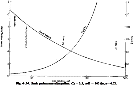
In almost any paper on the design analyses of VTOL aircraft in which different configurations are compared a graph reflecting the static perform-
ance of propellers can be found. This graph usually takes the form of static thrust capability (lb/hp) versus disk loading (lb/sq ft). Not to be outdone, this book includes such a graph (see Fig. 4-14), which was prepared in the following manner.
First, from experience it is known that the induced power is approximately 15% higher than that predicted by momentum theory. Second, it is assumed
![]()
|
|
|
|
|
|
|
|
|
|
|
|
|
|
|
|
|
|
|
|
|
|
|
|
|
|
|
and equipped with a 6 ft-diameter propeller with the characteristics of Fig. 4-11, what will be its maximum speed?
2. What would Fmax be for the aircraft of Problem 1 equipped with an ideal propeller with no profile drag?
3. Given the propeller in Fig. 4-12, estimate the section C, for a J of 1.0 at r = 3R/4. Note that /1 is the pitch angle of the chord line.
4. Estimate the initial acceleration of the aircraft in Problem 1 on takeoff.
5. A 10-bladed special-purpose propeller has a constant 10-in. chord and a 12% thick airfoil section and is designed to operate at an advance ratio of 1.5. Calculate the correction to the section angle of attack at a radius of 20 in. The propeller has a diameter of 6 ft.


