Autorotation
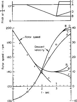
Helicopters are equipped with overriding clutches so that, in the event of power failure, the rotor will not be restrained by the engine but will be free to rotate. Immediately after a power failure the pilot must “dump” his collective pitch within two to three seconds. With decreased collective pitch, the rotor will autorotate as the helicopter begins to descend; that is, the aerodynamic forces on the rotor will cause it to rotate even though no mechanical torque is present. That such an aerodynamic torque can exist can be seen in Fig. 5-10. In descending, the resultant velocity is directed
і
Fig. 5-10. Blade section in descent.
upward by the combination of linear velocity from rotation (cor) and descent velocity (VD). The lift vector is therefore tilted forward with respect to the axis of rotation. If the angle tan-1 (VD/a>r) is too large, the section will stall and destroy the lift, hence the accelerating force; if this same angle is too small, the lift vector will not be tilted far enough forward to overcome the drag of the section and the force on the section will be a decelerating one. Thus in autorotation, in which the net aerodynamic torque on the rotor must be zero, only the middle portion of the blade produces an accelerating force. The inner portion is stalled, whereas the outer region near the tip produces a decelerating force. Figure 5-10 also shows why it is important to decrease collective pitch, for failure to do this will cause the blade to stall and the rpm to decay rapidly.
The successful emergence from a power failure is only secondarily dependent on the sink rate. It is dependent primarily on the ratio of the rotational energy stored in the rotating mass of the rotor to the translational energy of the helicopter. Ratios of rotor rotational energy to helicopter translational energy of the order of 3 or 4 have given satisfactory flare characteristics in practice.
The transition of a helicopter from hovering to unpowered vertical ascent has been the subject of many investigations. Most analyses are based on a numerical solution of the equations of motion of the rotor and the helicopter. Reference 9 presents a simplified analysis of the motion during transition which is valid for the first few seconds before pilot action or before too great a build-up in VD.
If T is the thrust produced by the rotor at any instant of time t, the acceleration of the aircraft in the downward vertical direction is given by
where W = helicopter weight.
The equation of motion of the rotor is
Ja> = Qs~ Qa,
where J = polar moment of inertia of the rotor, со = angular velocity,
Qs = shaft torque tending to increase,
Qa = aerodynamic torque tending to decrease со.
For complete power failure Qs = 0. If it is assumed that the collective pitch of the rotor will remain unchanged and the vertical descent velocity is small in comparison to the rotor tip speed, the dimensionless thrust and power (or torque) coefficients will remain constant. Assuming that CT and CQ are constant, we obtain
where
![]() Q pVfaR3’
Q pVfaR3’
QS0 = Qs for t < 0.
do da)’ dt’ da) o’QS0
dt dt’ dt do’ J
o’ = —ft)’2.
The solution to this equation is

![]()
![]()
 |
o’ = (1 + I’)"1-
Substitution of Eq. (5-19) into the equation produces
This equation can be integrated to yield
1 + t’
I = 1 -£ + ^log(l + 0, (5-21)
where
V = gt,
h = igt2.
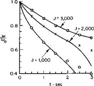
The figures in Ref. 9 are reproduced here as Figs. 5-1 la and 5-1 lb. Observe that the approximate equations (5-19), (5-20), and (5-21) agree well with the more refined calculations for the first few seconds.
If the log term in Eq. (5-21) is expanded for small values of t’, this equation becomes
|
|
|
|
|
|
|
which demonstrates the importance of having a high ratio of rotor angular momentum to rotor shaft torque. The higher the ratio, the smaller the amount by which the helicopter would fall in a given time.


