Simplified Theory of Forward-Flight
Consider the induced power required for sustaining lift with an elliptic wing.
Pi = Div = La, V
= Lw,
where P, = induced power,
D, = induced drag,
a, = induced angle of attack,
L = lift,
w — velocity induced at the wing.
These results show that the induced power is equal to the product of the
lift and the induced velocity. The induced velocity for an elliptic wing was derived in Chapter 3 and is given by
Because the aspect ratio is AR = b2/S, the above equation can be written as
L = (2w),
where b equals the wing span.
 |
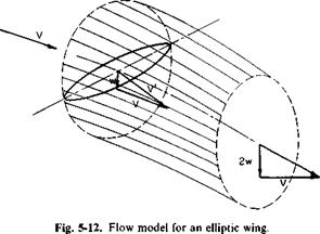
In words this equation states that the lift of an elliptic wing is equal to the product of twice the induced velocity and the mass rate of flow passing
through a circle with a diameter equal to the span of the wing and lying in a plane normal to V. This is illustrated in Fig. 5-12.
This same concept is now applied to a lifting rotor in forward flight; that is, the thrust and downwash at the rotor are related by assuming that
T = pVnR22w. (5-22)
The induced power then becomes
![]() P, = Tw T2
P, = Tw T2
~ IpVnR2
If, in addition, the thrust vector is tilted forward through a small angle a,
useful work is being performed at the rate of TaV. Thus, in general, the ideal power required by a rotor in forward flight is
![]() P = TaV + Pj = T(aV + w).
P = TaV + Pj = T(aV + w).
From Fig. 5-12 it can be seen that (aV + w) is simply the resultant velocity normal to the rotor disk plane. Thus, in words, it can be stated that the ideal power is given by the product of the thrust and the velocity normal to the disk.
In addition to this ideal power, the rotor requires a certain amount of power to overcome the profile drag of the rotor blade sections. This power, which is covered in some detail later, is referred to as profile power.
For steady forward flight the forward horizontal component of thrust Та must equal the parasite drag of the helicopter. Thus TaV is termed the parasite power and is equal to
iV = DV.
The total power required by a helicopter rotor in forward flight can now be seen to be composed of three parts.
![]() P = Pi + Pp&T + Pp = (induced) + (parasite) + (profile)
P = Pi + Pp&T + Pp = (induced) + (parasite) + (profile)
Equation (5-22), as proposed by Glauert, is written more specifically as
![]() T = pV’nR22w;
T = pV’nR22w;
V is the vector sum of v and w as shown in Fig. 5-12.
It is difficult to draw an analogy between this equation and the elliptic wing, but it has the advantage of agreeing with the hovering rotor in one limit as V -*• 0 and the elliptic wing at the other extreme as w/V -» 0. From this equation w can be obtained as
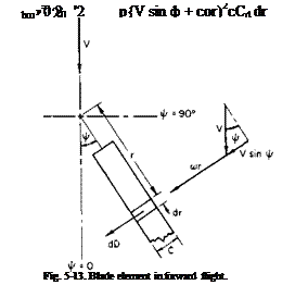
Profile Power. Consider the drag of a blade element in Fig. 5-13. The differential drag on this element is
dD = jp(V sin ф + a>r)2cCd dr.
In one complete revolution the work performed by dD is
The average power is equal to the work divided by the time required for one revolution. Hence the average power for b blades is
 |
or for the profile power
For a constant value of c and an assumed constant value of Cd, this becomes

![]() 4
4
x(p sin ф + x)2 dx dф о
= Po( 1 + p2)
where P0 = profile power required in hover (p = 0),
= V/coR.
|
(*R |
In adddition to overcoming the torque produced by the profile drag of the blades, more parasite power is required because of the blade profile drag:
Because it has the same form as profile power, this increment is usually included there, and Pp becomes
Pp = P0( 1 + іц2). (5-27)
The constant 3 in front of ц2 has become somewhat of a “fudge factor” and varies from manufacturer to manufacturer. Because of the aerodynamic uncleanliness of the root end of the rotor blades, this constant is usually increased in practice to 4 or more.
By expressing Pp as a function of ц and P0, we lessen the objection of assuming a constant Cd value, for P0 can be determined accurately without the use of such an assumption.


