Thrust augmentation and deflection of jets from turbo-jet engines
For many V/STOL missions the utilization of turbo-jet engines appears promising. This is particularly true for missions requiring short hovering times in which the low specific weight (pounds of engine weight per pound of thrust) offsets the disadvantages associated with the high disk loading such as high jet velocities and high specific fuel consumption (pounds of fuel per hour per pound of thrust). Also, for supersonic aircraft the required thrust – to-weight ratio of the power plant can exceed unity anyway, and all that is needed for adding V/STOL capability to these aircraft are the necessary controls and nozzles for vectoring the jets from the engines.
Thrust Augmentation
The thrust from a turbo-jet engine, particularly at low speeds or in the static case, can be augmented by passing the jet through a nozzle or a
|
Fig. 11.1. Thrust augmentation of a turbo-jet. |
series of nozzles. The primary flow from the jet induces a secondary flow of air through the nozzles, thereby developing a thrust on the nozzles. This is shown schematically in Fig. 11-1. The entrainment of the secondary flow is
280
produced by the high viscous shear and turbulent mixing that occurs along the boundary of the jet. For this reason the performance of the system depends not only on the geometry of the system but also on the Reynolds number of the jet.
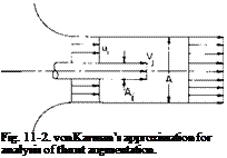 |
A relatively simple approach to the analysis of a thrust augmenter was suggested by von Karman in Ref. 1. Consider the simple jet-nozzle combination shown in Fig. 11-2. It is assumed that the exiting flow has been completely mixed so that the exiting velocity is uniform. The problem is to calculate the ratio of the total thrust to the jet thrust. This ratio, denoted by ф, is called the thrust augmentation ratio. The area of the nozzle is taken to be constant and equal to A. The area of the jet is denoted by Aj and its velocity by vf, u1 is the velocity of the secondary flow in the plane of the jet, whereas u2 is the uniform velocity issuing from the nozzle. It is further
assumed that the pressure at the nozzle exit is equal to the undisturbed static pressure, and p1 is the static pressure at the jet exit.
From continuity
u^A – A+ VjAj = u2A. (11-1)
Application of the momentum theorem between the jet exit and the nozzle exit results in
APi ~ Po) = PuA – pvjAj – pu(A – Aj). (11-2)
Also Bernoulli’s equation can be written outside the entrance up to the plane of the jet before mixing occurs.
Po = Pi + ipul – (11-3)
From these equations, eliminating n, and pu
![]() u2 — q(l — 2a) + yj2a — 6a.2 + 6a3 — 2a4,
u2 — q(l — 2a) + yj2a — 6a.2 + 6a3 — 2a4,
Vj 1 – 2a + 2a2
where a = Aj/A. The augmentation can then be calculated from
![]() puA
puA
PVjAj
![]() (и2/у/
(и2/у/
a
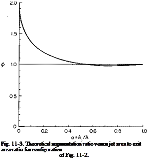 |
Because (11-5) represents complete mixing, it is the maximum augmentation to be expected from such a jet nozzle configuration; ф is shown as a
function of a in Fig. 11-3. It can be seen that ф drops off rapidly with increasing values of a for values of a below approximately 0.1 and is less than unity for a greater than j.
 |
||
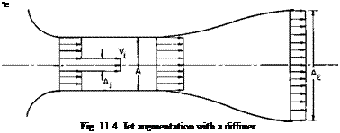
Theoretically, ф can be increased by the addition of a diffuser after the nozzle, as shown in Fig. 11-4. If it is assumed that the mixing is complete at the end of the cylindrical section and that Bernoulli’s equation holds in the diffuser, the ratio of the exit velocity VE to the jet Vj can be found in a manner similar to that used to obtain Eq. (11-4).
|
ф is then calculated from |
a _ PV*A£ PvjAj |
|
|
-(-)4 |
(11-7) |
|
|
vjJ a |
||
|
where p = Ae/A. |
|
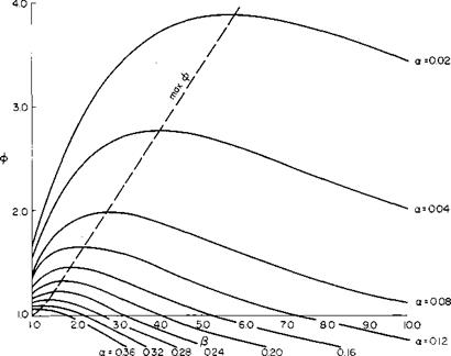
Equations (11-6) and (11-7) have been evaluated for combinations of a and p; ф as a function of P is given in Fig. 11-5 for constant values of a. For |
a constant value of a it can be seen that as j8 is increased <f> reaches a maximum value and then decreases for further increases in p. This graph clearly demonstrates the possible gains to be achieved by diffusion, particularly for small a-values.
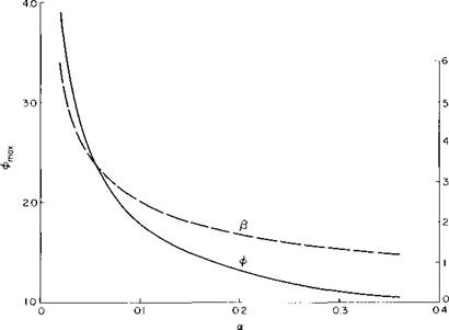
Figure 11-6, taken from Fig. 11-5, presents the maximum augmentation ratio obtainable with diffusion as a function of a. Also shown on the graph is the diffusion area ratio that gives the maximum ф.
The foregoing developments represent only one approach to predicting the performance of a thrust augmenter. Other analyses accounting for the thermal properties and compressibility of the working medium have been made in which the enthalpy of the mixed secondary and primary flow is assumed to be equal to the enthalpy of the entering primary flow.
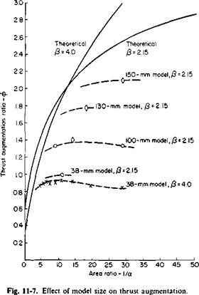
The predictions in Fig. 11-5 appear to represent an upper limit on ф difficult to attain in practice. Both Reynolds number and compressibility effects have a pronounced influence on the performance of a thrust augmenter, as pointed out in Ref. 2. At high Mach numbers the primary jet expands after leaving the nozzle, thus giving an effectively greater oc. At low Reynolds numbers the mixing of the primary and secondary flows is incomplete. This is illustrated in Fig. 11-7, taken from Ref. 2 (Fig. 5-5).
Here, measured and theoretical values of ф are compared as a function of
|
Fig. 11-5. Thrust augmentation ratio as a function of a and /?. |
|
Fig. 11-6. Theoretical maximum augmentation ratio and optimum diffuser area ratio. |
 |
 |
 |
1/a for a series of nozzles all having a diffuser area ratio [S of 2.15 (with the exception of the one small nozzle). It is apparent from this figure that, as the model size increases, the experimental results are approaching the theoretical values. Unfortunately, it is not entirely certain exactly what the Reynolds
numbers and Mach numbers were for the data of this figure. For the smaller nozzles the Reynolds number based on the primary velocity of the jet was approximately 8000, with a corresponding Mach number of about 0.8. It is believed that the Mach numbers are comparable for the larger models and that the improved performance of the larger models is probably attributable to Reynolds number effects.
A word of caution is called for here regarding this data, for the results are rather attractive for the larger models. These data are for the Coanda nozzle shown in Fig. 11-8. Instead of being injected centrally, the primary jet is injected around the periphery of the inner nozzle wall and follows the wall around in the downstream direction (the Coanda effect). Efficient mixing can occur for this configuration for a given primary mass rate of flow because of the large surface area of the primary jet. Were the same amount of fluid injected centrally, the performance would probably not be so good. As already mentioned, the Reynolds number for this nozzle is based on the primary jet velocity. The characteristic length used was the diameter of the nozzle throat.
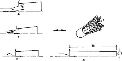
The secret of success for thrust augmentation by secondary flow entrainment appears to lie in the provision of a primary jet with a large surface area so that adequate mixing of the two streams is ensured. Some configurations that accomplish this mixing are described in Ref. 3 and shown in Fig. 11-9.
|
|
|
Fig. 11-9. Various types of thrust augmenters: (a) annular ring; (b) three annular rings; (c) radial; (d) seven divergent injectors; (e) multi-inline; (/) NACA (Morrison). |
|
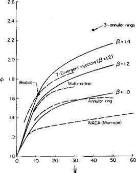
Fig. 11-10. Performance of various thrust augmenters:—————– theory;————- experiment. |
|
Fig. 11-11. The Lockheed Hummingbird—an aircraft that utilizes jet thrust augmentation by secondary flow entrainment. (Lockheed Aircraft Co.) |
Here, the primary jet is issued in the form of sheets through radial slots or concentric rings. The performance of these augmenters is described in Fig. 11-10. Observe that these augmenters incorporate diffusers that also seem to be a requirement for high augmentation ratios. Indeed, the long cylindrical nozzle of the lower augmenter on this graph probably has in effect a p less than unity because of the boundary layer growth on the nozzle walls.
From the theoretical and experimental results presented here it appears possible to augment the thrust from a jet appreciably by entrainment of secondary flow. Whether it is practicable to achieve values much in excess of 2 remains to be seen. The types of primary nozzle shown in Fig. 11-9 are certainly promising, but even here there may be a total pressure loss that will detract somewhat from the 0-values of Fig. 11-10.
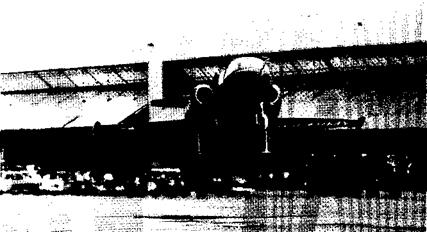
Thrust augmentation has been utilized in one aircraft to date (see Fig. 11-11). In Ref. 4 а ф of 1.24 is quoted for this aircraft.


