The Deflection of a Jet by a Cascade of Airfoils
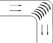
Whether augmented or nonaugmented, the momentum in the exhaust of a turbo-jet must be turned for VTOL applications in order to attain a vertical component of its thrust. This is in lieu of rotating the entire engine. Figure 11-12 is a sketch of the jet being turned by a cascade of airfoils in a
|
Fig. 11-12. Flow turned in a duct by a cascade of airfoils. |
duct. This section treats the basic aerodynamics of such a cascade without being concerned with any one particular cascade or design configuration for diverting the jet at different angles.
We begin by placing a doubly infinite two-dimensional vortex sheet in a uniform flow, as shown in Fig. 11-13. Either by application of the Biot – Savart law and integration over the vortex from x = — oo to + oo or by consideration of the circulation around a dashed path, the velocity induced
by the sheet is purely tangential to the sheet and is constant, independent of the distance from the sheet, and has a value of
М=Д. (11-8)
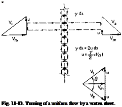 |
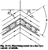
This velocity reverses direction discontinuously through the vortex sheet. The uniform и adds to the uniform velocity Vm and produces the streamline
pattern shown in Fig. 11-14. We can replace two of the streamlines by solid boundaries, thus generating a flow being turned through an angle в in a duct. Notice that the velocity Vm does not exist anywhere in the duct except in the plane of the vortex sheet.
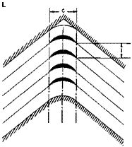
Let us now replace the vortex sheet by a finite number of airfoils in cascade spaced a distance of t apart, as shown in Fig. 11-15. If Г is the circulation around any one airfoil, then from (11-8) the velocity и will be
Г
и = —•
2t
For an inviscid fluid the resultant force on the vanes can be normal only to Vm. For each vane, by applying the momentum theorem,
![]() L = pVmt2u
L = pVmt2u
or, from the Kutta-Joukowski law,
L = pVm Г
= pVJ2ut).
In terms of a vane lift coefficient,
L = У VicC,
or, using (11-9),
C-4(B’ ,1M0)
where a is the cascade solidity,
![]() (11-11)
(11-11)
 |
 |
Hence the lift coefficient of each vane increases as the turning increases or the solidity decreases.
Now let us go back to the vortex sheet, but this time let us place the plane of the sheet at an angle Pm different from 0 to the velocity Vm, as shown in Fig. 11-16. By writing Bernoulli’s equation from the left duct to the right duct we can obtain the pressure decrease across the cascade as
Pi ~ P2 = 2PuVm sin Pm-
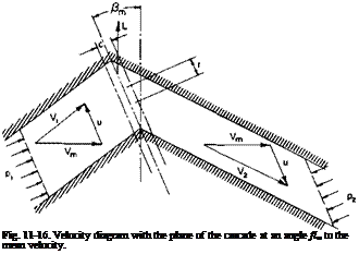
By application of the momentum theorem or by use of the Kutta-Joukowski
law it is apparent that the resultant force on the cascade is still normal to the mean velocity Vm and for one vane is given by
L = pVm Г
= pVJlut).
Again, if we let L = ^pV„cCh then
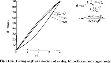
Hence C, for the same solidity, and и is not a function of the angle fim. However, from the geometry of Fig. 11-16 the angle through which the flow is turned is given by
This relationship is presented graphically in Fig. 11-17 as a function of <rC, for various values of /?m. Notice that regardless of a value of <rC, = 4 will produce a turning angle of 90°.
![]()
|
Hence for a given C, the turning angle decreases as /?m departs from 0. However, there is something to be gained by having a /?m greater than 0, corresponding to Fig. 11-16. This is the fact that in such a cascade the flow is accelerating and has a favorable pressure gradient. Hence the
|
Fig. 11-19. Effect of solidity on С,(ттяІ and L/D. |
frictional losses and the maximum C„ both dependent on the boundary layer growth, may be improved with a greater than zero.
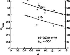
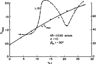
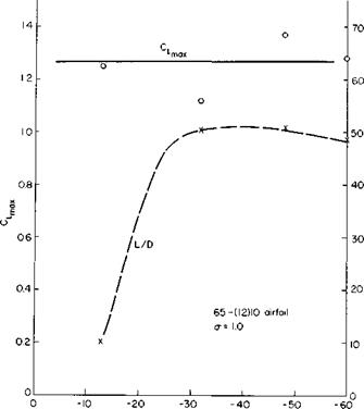
Figures 11-18,11-19, and 11-20 summarize the data of Ref. 6. As presented in the reference, these data are based on and the resultant inlet velocity. When reduced on the basis of Vm and /?m, as shown here, the data are very
|
|
|
Fig. 11-21. Effect of drag on total pressure. |
revealing. Figure 11-18 shows little or no variation of C, maii with the angle Pm for constant solidity and camber. The preceding paragraph suggested a possible improvement of C, max as fim becomes more positive. The L/D curve even shows the opposite trend with /?m. However, the L/D data are somewhat erratic and should be viewed with caution. In general, the safest statement would be to say simply that most of the L/D values at C, max range between 20 and 60. The importance of L/D is discussed later.
Figure 11-19 shows the effect of varying the solidity while keeping f}m and the camber constant. Although there is some scatter, there is a definite trend for C, max to increase with decreasing solidity.
The effect of varying camber, keeping solidity and f}m constant, is shown in Fig. 11-20. As expected, C, max increases with increasing camber and, at least for this a and /?ш, shows no sign of leveling out as z is increased.
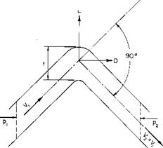
The drag of the cascade in turning the jet produces a loss in the total pressure of the flow, hence in the thrust that can be produced by the jet. To obtain an expression of the relative decrease in the thrust in terms of the cascade drag, let us consider only the particular case in which the jet is turned through 90°. From Fig. 11-21, since Vl = V2, we can write
ІРі ~ Pi)t – D = 0.
Thus, in dimensionless form, the decrease in total pressure across the cascade is
|
Ap D
|
|
|
Now consider a jet flow with a mass flow rate m and a total pressure of Pi + hpV- By expanding this jet to ambient pressure for incompressible flow we obtain a jet velocity of
/Pl — Po + lPv i‘
" 4hP
If the total pressure is now decreased by Ap, the reduced jet velocity will be
The decrease in the jet momentum flux as a fraction of the original flux therefore is
AT
T
Using (11-14) and assuming the fractional decrease to be small, we obtain
![]()
![]() 2
2
Finally, in terms of the resultant velocity in the duct Fj, the fractional decrease in the jet thrust after substituting for C, is
![]()
![]() (11-15)
(11-15)
The ratio of VJ depends on the particular design of the duct. For a straight duct VJv} might be about 1.0. If the cascade were located in a short duct right behind a propeller, VJ vj would be about j for the static case.
Reference 7 is a study of the design of turning vanes for miter bends at the corners of a water tunnel. The criteria for these vanes are nearly identical to those for turning a high velocity jet of air. The Reynolds number is high, the flow is turned through 90° with a minimum loss, and low pressure peaks
are to be avoided (to prevent cavitation in water or low Mcr in air). According to the reference, the optimum solidity is about 1.9. For R = 1.2 x 10⁶ based on Vl and the vane chord the following pressure loss coefficients are reported for two different solidities :
a = 1.89, Cp = 0.13,
a = 0.943, Cp = 0.26,
where Cp = Ap/jpV.
From the preceding developments the drag-to-lift ratios are half the above Cp values, or £ = 0.065 and 0.13 for the higher and lower solidities,
|
|
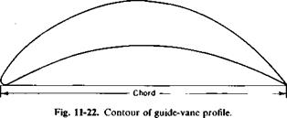
respectively. Note that because aC, = 4.0 for в of 90° the higher solidity corresponds to a C, of 2.12. These results are fairly well in line with the data of Ref. 6. A drawing of the vane, selected from Ref. 7, is shown in Fig. 11-22. The drawing is to scale.
From this data, it would appear that the frictional loss in thrust due to turning the jet through 90° will be of the order of 5%, depending on the ratio of V1 to Vj. This may not seem to be too much, but as a percentage of the payload it may be a deciding factor.


