Our heavyweight helicopter equal in the world does not have
In Rostov started production of the most load-lifting rotary-wing car The Russian holding «Helicopt[...]

Everything about aircrafts and helicopters. News and events in aviation worldwide. Civil, transportation, military helicopters and airplanes.

Everything about aircrafts and helicopters. News and events in aviation worldwide. Civil, transportation, military helicopters and airplanes.

Everything about aircrafts and helicopters. News and events in aviation worldwide. Civil, transportation, military helicopters and airplanes.

Everything about aircrafts and helicopters. News and events in aviation worldwide. Civil, transportation, military helicopters and airplanes.


Of the 24 control derivatives, we have selected the 11 most significant to discuss in detail and have arranged these into four groups: collective force, collective moment, cyclic moment and tail rotor collective force and moment.
The derivatives Z00, Zви
 |
|
The derivative of thrust with main rotor collective and longitudinal cyclic can be obtained from the thrust and uniform inflow equations already introduced earlier in this chapter as eqns 4.66, 4.67. Approximations for hover and forward flight can be
From the derivative charts in the Appendix, Section 4B.2, it can be seen that this Z-force control derivative doubles in magnitude from hover to high-speed flight. This is the heave control sensitivity, and as with the heave damping derivative Zw, it is primarily influenced by the blade loading and tip speed. The reader is reminded that the force derivatives are in semi-normalized form, i. e., divided by the aircraft mass. The thrust sensitivity for all three case aircraft is about 0.15 g/° collective. Unlike the heave damping, the control sensitivity continues to increase with forward speed, reflecting the fact that the blade lift due to collective pitch changes divides into constant and two-per-rev components, while the lift due to vertical gusts is dominated by the one-per-rev incidence changes.
The thrust change with longitudinal cyclic is zero in the hover, and the approximation for forward flight can be written as
As forward speed increases, the change in lift from aft cyclic on the advancing blade is greater than the corresponding decrease on the retreating side, due to the differential dynamic pressure. As with the collective derivative at higher speeds, Ze1s increases almost linearly with speed, reaching levels at high speed very similar to the collective sensitivity in hover.
The derivatives M6o, Lво
Pitch and roll generated by the application of collective pitch arise from two physical sources. First, the change in rotor thrust (already discussed above) will give rise to a moment when the thrust line is offset from the aircraft centre of mass. Second, any change in flapping caused by collective will generate a hub moment proportional to the flap angle. It is the second of these effects that we shall focus on here. Referring to the flap response matrices from Chapter 3 (eqn 3.70), we can derive the main effect of collective pitch on flap by considering the behaviour of a teetering rotor at moderate forward speed. Hence we assume that
The aft flapping from increased collective develops from the greater increase in lift on the advancing blade, than on the retreating blade in forward flight. The effect grows in strength as forward speed increases, hence the approximate proportionality with speed. From the charts in the Appendix, Section 4B.2, we can observe that the effect is considerably stronger for the hingeless rotor configurations, as expected. In high-speed flight, the pitching moment from collective is of the same magnitude as the cyclic moment, illustrating the powerful effect of the differential loading from collective. Increasing collective also causes the disc to tilt to starboard (to port on the Puma). The physical mechanism is less obvious than for the pitching moment and according to the approximation in eqn 4.100, the degree of lateral flap for a change in collective pitch is actually a function of the rotor Lock number. The disc tilt arises from the rotor coning, which results in an increase in lift on the front of the disc and a decrease at the rear when the blades cone up (e. g., following an increase in collective pitch). The amount of lateral flapping depends on the coning, which itself is a function of the rotor Lock number. Once again, the resultant rolling moment will depend on the balance between thrust changes and disc tilt effects, which will vary from aircraft to aircraft (see control derivative charts in the Appendix, Section 4B.2).
The derivatives M01s, Mgu, Lвъ, Lвіс
The dominant rotor moments are proportional to the disc tilt for the centre-spring equivalent rotor and can be written in the form
Mr ~-(NTKe + hR^j etc, Lr «-(NbKp + hRT^j Plt (4.101)
The cyclic control derivatives can therefore be approximated by the moment coefficient in parenthesis multiplied by the flap derivatives. We gave some attention to these functions in Chapter 2 of this book. The direct and coupled flap responses to cyclic
|
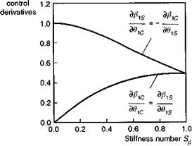
Fig. 4.22 Variation of rotor flap derivatives with Stiffness number |
control inputs are practically independent of forward speed and can be written in the form
where the Stiffness number is given by eqn 4.59. The variations of direct and crosscoupled flap derivatives with stiffness were illustrated in Fig. 2.21 (a), and are repeated here as Fig. 4.22 for the reader’s convenience. Up to Stiffness numbers of about 0.3 the direct flap derivative remains within a few percent of unity. The implication is that current so-called hingeless or ’semi-rigid’ rotors (e. g., Lynx and Bo105) flap in much the same way as a teetering rotor following a cyclic control input -1° direct flap for 1° cyclic. The cross-flap derivative arises with non-zero stiffness, because the natural frequency of flap motion is then less than one-per-rev, resulting in a flap response phase of less than 90°. The phase angle is given by tan-1 Sp, hence varying up to about 17° for Sp = 0.3. Although the cross-control derivative can be, at most, about 30% of the direct derivative, when considering pitch to roll coupling, this can result in a much greater coupled aircraft response to control inputs, because of the high ratio of pitch to roll inertias. This is evidenced by the coupling derivative Lq1s for the Lynx andBo105 in the charts of the Appendix, Section 4B.2, which is actually of higher magnitude than the direct control moment Me1s. The aircraft will therefore experience a greater initial roll than pitch acceleration following a step longitudinal cyclic input. The cyclic controls are usually ‘mixed’ at the swash plate partly to cancel out this initial coupling. We have already discussed the cross-coupling effects from pitch and roll rates and, according to the simple rotor theory discussed here, the total short-term coupling will be a combination of the two effects.
The derivatives Y6ot, Lвот, NgOT
According to the simple actuator disc model of the tail rotor, the control derivatives all derive from the change in tail rotor thrust due to collective pitch. As with the derivatives Nv and Nr, the control derivative also decreases by as much as 30% as a result of the action of a mechanical S3 hinge set to take off 1° pitch for every 1° flap. The exact value depends upon the tail rotor Lock number. In the derivative charts in the Appendix, Section 4B.2, we can see that the force derivative YeOT for the Bo105 is about 20% higher than the corresponding values for the Lynx and Puma. The Bo105 sports a teetering tail rotor so that the S3 effect works only to counteract cyclic flapping. The control derivatives increase with speed in much the same way as the main rotor collective Z-force derivative, roughly doubling the hover value at high speed as the V2 aerodynamics take effect.
The effects of non-uniform rotor inflow on damping and control derivatives
In Chapter 3 we introduced the concept of non-uniform inflow derived from local momentum theory applied to the rotor disc (see eqns 3.161, 3.181). Just as the uniform inflow balances the rotor thrust, so the flow needs to react to any hub moments generated by the rotor and a first approximation is given by a one-per-rev variation. The nonuniform inflow components can be written in the form given by
![]() x1c = (1 — C1) (ftc — ft* + q)
x1c = (1 — C1) (ftc — ft* + q)
ft* = (1 – C1) (01* – ftc + p)
where the lift deficiency factor in the hover takes the form
The non-uniform inflow has a direct effect on the flapping motion and hence on the moment derivatives. The effect was investigated in Refs 4.20 and 4.21 where a simple scaling of the rotor Lock number was shown to reflect the main features of the hub moment modification. We can write the flap derivatives as a linear combination of partial effects, as shown for the flap damping below:
![]() d^1c l Эв1Л Эв1с ЭА.1* Эв1с дХ1с
d^1c l Эв1Л Эв1с ЭА.1* Эв1с дХ1с
dq v dq Jut 9Л1* dq dX1c dq
The subscript ui indicates that the derivative is calculated with uniform inflow only. Using the expressions for the flap derivatives set down earlier in this section, we can write the corrected flap derivatives in the form
Se 16
P1cq = в1*р = g + ^ + Se C2 в1*9 (4.108)
P1*q = ~P1cp = g – SP^- SP C2 вЩ (4.109)
where the equivalent Lock number has been reduced by the lift deficiency factor, i. e.,
Y * = C1Y (4.110)
and the new C coefficient is given by the expression
![]()
(4.111)
Equation 4.108 shows the first important effect of non-uniform inflow that manifests itself even on rotors with zero hub stiffness. When the helicopter is pitching, the rotor lags behind the shaft by the amount given in eqn 4.108. This flapping motion causes an imbalance of moments which has a maximum and minimum on the advancing and retreating blades. This aerodynamic moment, caused by the flapping rate, gives rise to a wake reaction and the development of a non-uniform, laterally distributed component of downwash, к 1 s, serving to reduce the incidence and lift on the advancing and retreating blades. In turn, the blades flap further in the front and aft of the disc, giving an increased pitch damping Mq. The same arguments follow for rolling motion. The effect is quite significant in the hover, where the lift deficiency factor can be as low as 0.6.
By rearranging eqns 4.108 and 4.109, we may write the flap derivatives in the
 |
||
form
where the third C coefficient takes the form
and can be approximated by unity.
The new terms in parentheses in eqns 4.112 and 4.113 represent the coupling components of flapping due to the non-uniform inflow and can make a significant contribution to the lateral (longitudinal) flapping due to pitch (roll) rate, and hence to the coupled rate derivatives Lq and Mp.
A similar analysis leads to the control derivatives, which can be written in the forms
P1ce 1s —~P1se1C — – C3 (1 — C2Sj) (4.115)
fhce 1c — P1se 1s — C3 Cl (4.116)
C1
In the hover, for a rotor with zero flap stiffness, the aerodynamic moment due to flapping is exactly equal to that from the applied cyclic pitch; hence there is no non-uniform inflow in this case. The coupled flap/control response, given by eqn 4.116, is the only significant effect for the control moments indicating an increase of the coupled flapping of about 60% when the lift deficiency factor is 0.6.
Some reflections on derivatives
Stability and control derivatives aid the understanding of helicopter flight dynamics and the preceding qualitative discussion, supported by elementary analysis, has been
aimed at helping the reader to grasp some of the basic physical concepts and mechanisms at work in rotorcraft dynamics. Earlier in this chapter, the point was made that there are three quite distinct approaches to estimating stability and control derivatives: analytic, numerical, backward-forward differencing scheme and system identication techniques. We have discussed some analytic properties of derivatives in the preceding sections, and the derivative charts in the Appendix, Section 4B.3, illustrate numerical estimates from the Helisim nonlinear simulation model. A discussion on flight estimated values of the Bo105 and Puma stability and control derivatives is contained in the reported work of AGARD WG18 – Rotorcraft System Identification (Refs 4.22, 4.23). Responses to multistep control inputs were matched by 6 DoF model structures by a number of different system identification approaches. Broadly speaking, estimates of primary damping and control derivatives compared favourably with the Level 1 modelling described in this book. For cross-coupling derivatives and, to some extent, the lower frequency velocity derivatives, the comparisons are much poorer, however. In some cases this can clearly be attributed to missing features in the modelling, but in other cases, the combination of a lack of information in the test data and an inappropriate model structure (e. g., overparameterized model) suggests that the flight estimates are more in error. The work of AGARD WG18 represents a landmark in the application of system identification techniques to helicopters, and the reported results and continuing analysis of the unique, high-quality flight test data have the potential for contributing to significant increased understanding of helicopter flight dynamics. Selected results from this work will be discussed in Chapter 5, and the comparisons of estimated and predicted stability characteristics are included in the next section.
Derivatives are, by definition, one-dimensional views of helicopter behaviour, which appeal to the principle of superposition, and we need to combine the various constituent motions in order to understand how the unconstrained flight trajectory develops and to analyse the stability of helicopter motion. We should note, however, that superposition no longer applies in the presence of nonlinear effects, however small, and in this respect, we are necessarily in the realms of approximate science.