Criteria for hover and low-speed flight
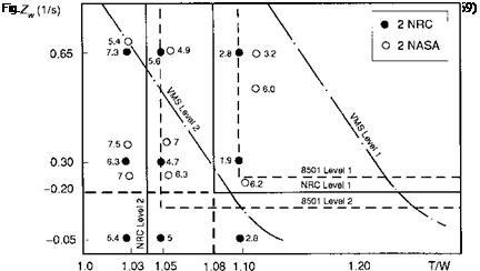
The work reported in Refs 6.65 and 6.66 generally supported the use of VSTOL aircraft formats and an early version of the revision to MIL-H-8501 placed the boundaries on time domain parameters – rise time, response shape and control sensitivity, based on the height rate response to a step collective input. The lower boundary for Level 1/2 handling corresponded to a vertical damping Zw of -0.25 / s centred around a collective sensitivity of 0.4 g/in. Later tests conducted on the NASA VMS (Ref. 6.68) and at the Canadian Flight Research Laboratories (Ref. 6.69) demonstrated the importance of thrust to weight (T/W). A new format, based on T/W, was proposed with revised heave damping boundaries (Fig. 6.54). The Canadian trials provided a range of new insights into rotorcraft vertical axis handling. First, for the bob-up task, the required heave damping for Level 1 handling qualities appeared to be independent of T/W down to the boundary at 1.08 (i. e., 8% thrust margin), provided that the damping was above the minimum required value of 0.25; Level 2 handling could be achieved with thrust margins greater than 4%, for any value of damping, down to zero. Second, the response shape criteria discussed earlier appeared to have little significance in determining Level 1
handling qualities for low values of T/W typical of rotorcraft loaded to their mission gross weights. Third, the dynamics of the torque response, and particularly the dynamic response of the cockpit-displayed torque, significantly affected pilot control strategy and hence handling qualities, emphasizing the need for criteria relating to this effect. Fourth, pilots preferred a collective control sensitivity linearly matched to the heave damping such that the ratio was a constant. Fifth, the boundaries on the damping/thrust margin charts, suggested by the earlier NASA VMS trials (Ref. 6.66), actually sloped a different way; the results from NRC flight trials suggested that as the damping increased, the thrust margin should at least be held constant and possibly increase, to give the pilot a similar level of climb performance. There is a definite trade-off involved here – performance versus stability – and the flight data favours the former, at least for the bob-up task. Reference 6.69 argues that in ground-based simulation experiments, pilots have greater difficulty with the stabilization task than in real flight due to deficient visual cues, hence biasing their preference towards greater stability. Finally, the level of augmentation in pitch and roll had a significant effect on the workload capacity available for pilots to concentrate on the primary vertical axis task. These results fed into the development of the US Army’s military handling requirements, and a major revision to the height response criteria eventually appeared in ADS-33 (Ref. 6.5).
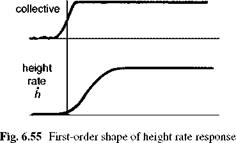
The current requirements on vertical axis response characteristics in Ref. 6.5 are based on the premise that the height rate response to a collective step input should have a qualitative first-order shape as shown in Fig. 6.55. Handling qualities parameters can be derived from a response model structure in the first-order form
![]()
 |
h _ Ke W
Sc Th s + 1
heq
where h is the height, Sc the pilot’s collective lever and the estimated (time domain) handling qualities parameters should have values less than those given in Table 6.4.
|
|
|
Table 6.4 Maximum values for time parameters in height response to collective (Ref. 6.5)
|
The maximum acceptable value of the time constant Tjeq for Level 1 handling corresponds to a minimum value of heave damping of -0.2. The time delay is included in the model structure to account for actuation and rotor dynamic lags. The gain or control power K is determined from the steady-state response to the step input and, for the simple first-order representation, is given by the ratio of control sensitivity to damping. In ADS-33, the limits on vertical axis control power are expressed in terms of the achievable height rate in 1.5 s and are given in Table 6.5.
The requirements of Table 6.5 can be interpreted in terms of required hover thrust margins if it is assumed that the initial 1.5 s of height response takes the form of a first-order exponential function. The Level 1 requirements then correspond to a thrust margin of 5.5% while the Level 2 boundary lies at 1.9% at zero damping; both values are far lower than any previous results obtained in clinical flying qualities tests with the bob-up task. In this requirement we see a degree of conflict between current capabilities and future requirements. Most helicopters, whether civil or military, will carry the maximum allowed payload on a mission, and this generally leaves little margin for manoeuvring at low speed. As fuel burns off, the available excess thrust and power margins increase, but to insist on 8%, 10% or even higher margins at take-off can significantly reduce the payload and hence mission effectiveness from a productivity perspective. Thus, a compromise has been made in the performance requirements of vertical axis handling, in recognition of current operational practices. For increasing heave damping, the T/W has to increase to achieve the same vertical velocity, and the control power requirements of Table 6.5 can be interpreted as boundaries on Fig. 6.54. The lines again indicate the apparent preference for performance, rather than stability,
|
Table 6.5 Vertical axis minimum control power requirements (Ref. 6.5)
|
in MTEs like the bob-up. In contrast, preliminary results from DRA piloted simulation trials of ship landings in poor weather (Ref. 6.70) indicate that increased stability (damping) is preferred as T/W is reduced. The tentative results published in Ref. 6.70 suggest that in sea state 5 (typical worst operating conditions with deck motion ±2 m) a heave damping of -0.4 would be required with a T/W of 1.08.
The handling parameters in eqn 6.29 can be derived from a curve-fitting procedure defined in Ref. 6.5 and summarized below. This is the only criterion in ADS-33 that requires explicit parameter estimation from a model-fitting process. The technique and some examples have already been discussed in Chapter 5 of this book. In the present case the fitting process is classed as least squares, output error and is accomplished as follows:
(1) The helicopter is trimmed in hover and a step input in collective applied; measurements of height rate are obtained at 0.05-s intervals for a 5-s duration.
(2)
Setting initial values for the parameters in eqn 6.29, based on a priori knowledge, an estimate of the height rate is obtained from the solution to eqn 6.29
![]() hest — 0, t <t
hest — 0, t <t
The t > T requirement in eqn 6.30 is made to ensure that the response is causal, a point noted in Ref. 6.71.
(3) The difference between the flight measurement and the estimated height rate is constructed as an error function e(t) given by
101
®2 — D (hi — hi2 (6.32)
i—1
and the sum of squares of this error function is minimized by varying the parameter set K, Th and Th.
’ heq heq
|
E101 /. —2 i—1 (h i — h) where the mean value of measured height rate is given by – E101 hn h= ^i—1 |
(4)
 |
|
The goodness or quality of fit can be derived from the coefficient of determination given by
(5) For a satisfactory fit, the coefficient of determination should exceed 0.97 and be less than 1.03.
The LOES for low-speed heave axis handling qualities described above has evolved from a number of attempts to model important handling effects during the development
of ADS-33. It appears to capture, with a reasonably high degree of fidelity, the natural characteristics of unaugmented helicopter heave motion in the frequency range of pilot closed-loop control in manoeuvres like the bob-up and precision landing.
One final aspect of the response to collective concerns the shape of the normal acceleration following a very sharp control input. This subject was discussed in Chapter 5 and is also given some attention in Ref. 6.67. The delay in the build up of the rotor inflow causes the acceleration response to peak at much higher values than the ‘steady state’ (see Fig. 6.52). This ‘high order’ effect will be reflected in the height rate response and will ‘spoil’ the simple first-order character, with the potential consequence that the model parameters will be distorted, in trying to match the more complex response shape. One solution to this potential difficulty is to ensure that the pilot applies a ramp collective input over, say, a 1-s period, thus allowing the inflow time to develop during the input. This is an expedient measure to satisfy the low-moderate frequency requirements of the handling effects accommodated by eqn 6.29, but obscures any additional handling effects at higher pilot gains. We have already stated that control of vertical motion is largely a low-moderate gain task for the pilot, but automatic height-keeping controllers will typically have to work at much higher frequencies where the simple model structure given above will be inadequate. Raising this issue here highlights the different modelling requirements for handling qualities and control law design, a topic given some attention in Chapter 5 of this book.
6.5.1 Criteria for torque and rotorspeed during vertical axis manoeuvres
The vertical handling qualities research exercises at NASA Ames and the Canadian FRL, described in Refs 6.67 and 6.69, both highlighted the importance of monitoring rotor rpm and torque during MTEs like the bob-up. In some cases the monitoring requirements on the pilot dominated the workload and hence the pilot HQRs. This was particularly true for configurations with low T/W or with slow engine/rotorspeed governor systems leading to large excursions in rotorspeed. Various attempts were made to develop supplementary criteria relating to the response of these variables, but the findings from the available database were not entirely consistent. The eventual formats that were settled on for ADS-33 were of a qualitative form for rotorspeed governing, requiring transients to remain within limits for all tasks flown within the OFE, and a quantitative form for displayed torque as shown in Fig. 6.56. The Level 1/2 and 2/3 boundaries are based on the character of the displayed torque in terms of time to first peak and overshoot ratio. To the author’s knowledge, there are very few data in the open literature to validate the criterion set down in Fig. 6.56, and the topic has to be one of the weak areas of current handling criteria and, in view of its importance to pilot workload, in need of further research.


