
Our heavyweight helicopter equal in the world does not have
In Rostov started production of the most load-lifting rotary-wing car The Russian holding «Helicopt[...]

Everything about aircrafts and helicopters. News and events in aviation worldwide. Civil, transportation, military helicopters and airplanes.

Everything about aircrafts and helicopters. News and events in aviation worldwide. Civil, transportation, military helicopters and airplanes.

Everything about aircrafts and helicopters. News and events in aviation worldwide. Civil, transportation, military helicopters and airplanes.

Everything about aircrafts and helicopters. News and events in aviation worldwide. Civil, transportation, military helicopters and airplanes.


To a first, albeit rather crude, approximation, the response of a helicopter to an atmospheric disturbance can be measured in terms of the force and moment derivatives discussed in Chapters 1, 4 and 5 of this book. In Chapter 1, the heave response to a vertical gust was touched on, and expressions for the contributing derivative Zw were then developed in Chapter 4. The discussion was extended in Section 5.4 to the modelling of atmospheric disturbances and the subsequent ride qualities. Heave response tends to dominate the concern because the rotor is the dominant lifting component on a helicopter. As the forward velocity increases, the energy of the ‘gust response’ is absorbed more and more by the vibratory loading, since this dominates the component of lift proportional to forward speed. The heave response derivative, Zw, becomes asymptotic to the expression — pa<^lR as velocity increases (see eqn 5.79). This represents an approximation to the initial vertical bump when flying into a vertical gust and is proportional to rotor blade tip speed and inversely proportional to blade loading (ib). In comparison, as a fixed-wing aircraft flies faster, the product of dynamic pressure and incidence leads to a heave response proportional to forward velocity V (— PaO V) and inversely proportional to wing loading (lw). The charts and tables of derivatives at the end of Chapter 4 give a ‘feel’ for the magnitude of the gust response; a typical helicopter has a value of Zw of about 1 m/s2 per m/s at high speed, giving a 1-g bump when entering a vertical gust of magnitude about 10 m/s. On entering such a gust the aircraft would be climbing at 6.3 m/s after 1 s (t63% = — Z~) and would continue climbing, approaching 10 m/s asymptotically. Similarly, the response to flight through a variable gust field can be approximated by the aerodynamic components of the damping derivatives L p and Mq (the gyroscopic components in expressions like eqns 4.86-4.89 are not included, only the aerodynamic terms), assuming the gust field can be approximated by a linear variation across the rotor disc. Linear approximations
have been used extensively by the fixed-wing community to analyze and quantify the gust response of aircraft, and similar methods are available and used in helicopter design.
Very strong atmospheric disturbances, where linear models are questionable, should be avoided in operations where possible. However, there are some situations where a helicopter has to be flown through a vortex-infested, swirling flow-field to reach its landing site. The helicopter, recovering to a ship or helideck, having to fly through the airwake from the superstructure presents such an example. In Ref. 8.7 (see also Refs 8.51 and 8.52), the ship airwake was described as the ‘invisible enemy’ by virtue of the fact that a pilot is very vulnerable to the degraded handling qualities arising from the effects of the unseen, unsteady and swirling vortical flow structures in the lee of a ship’s superstructure, which commonly is where the helicopter landing deck is situated. Over the decade since the publication of the first edition of this book a considerable amount of research, typified by that reported in Refs 8.51 and 8.52, has been conducted to develop modelling and simulation capabilities able to predict the ship-helicopter operating limits (SHOLs) in the presence of the ship’s airwake. The kind of problem faced by operators is shown in the example of the Royal Navy’s Royal Fleet Auxiliary (RFA), which has two landing spots, spot 1 on the port side close to the hangar and spot 2 on the starboard side to the aft of the flight deck. The difference in the SHOLs for spots 1 and 2 is compared with the original requirement during procurement in Fig. 8.46 (Ref. 8.51). The SHOL is the shaded area on the polar
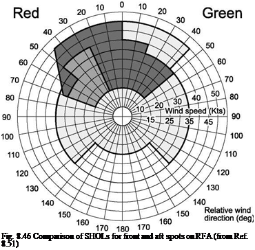 |
I I Requirement | | Current Helicopter Current Helicopter
RFA Spot 2 RFA Spot 1
plot of relative wind speed and direction. Although both are restricted, the SHOL for spot 1 makes it almost unusable in most wind-over-deck conditions. The problem is caused by the combination of the helicopter operating close to the hangar face at low heights and the airwake created by the geometry of the ship, the hangar and the flight deck. Mean and unsteady downwash velocity components are so high in this region that the pilot has difficulty taking off and hovering.
The SHOL is defined to allow operations to be conducted safely in the presence of disturbed atmospheric conditions and the additional difficulties associated with ship motion and degraded visibility. For the main discussion in this section of the chapter, we turn to a situation where operating limits are more difficult to define – the effect of fixed-wing aircraft trailing vortices on helicopter handling qualities.
