Our heavyweight helicopter equal in the world does not have
In Rostov started production of the most load-lifting rotary-wing car The Russian holding «Helicopt[...]

Everything about aircrafts and helicopters. News and events in aviation worldwide. Civil, transportation, military helicopters and airplanes.

Everything about aircrafts and helicopters. News and events in aviation worldwide. Civil, transportation, military helicopters and airplanes.

Everything about aircrafts and helicopters. News and events in aviation worldwide. Civil, transportation, military helicopters and airplanes.

Everything about aircrafts and helicopters. News and events in aviation worldwide. Civil, transportation, military helicopters and airplanes.


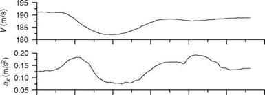
One of the purposes of acceleration and deceleration maneuver is to estimate the drag polars at high angles of attack. After trimming the aircraft, the pilot reduces the power to idle and decelerates to the minimum desired speed (a few knots above stall). He or she can hold altitude with only pitch control. Then the throttle is moved quickly to full power and the aircraft is allowed to accelerate. On reaching the maximum speed, the power is reduced to idle and the aircraft decelerates back to the starting trim speed. The maneuver should be performed smoothly. The overall altitude should not change more than 35 m. The power transition should be quite smooth.
2
 1
1
0
6
![]()
 |
3
0
-3 4 -6
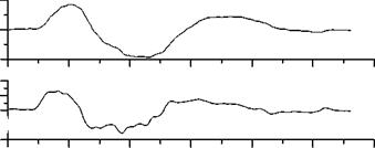
7.7.4 WUT Maneuver
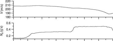
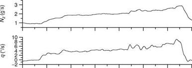
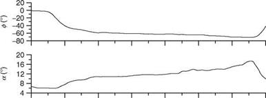
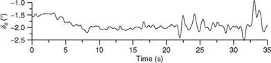
In WUT maneuver the pilot starts banking 2000 ft above the test altitude and then increases the load factor by pulling up slowly from 1g to the maximum permissible g at 0.5g to 0.8g/s rate. The speed is maintained by reducing the altitude and the throttle deflection is kept constant. This maneuver is useful to get the data for performance above M > 0.4 and from 1g to maximum g. Since bank angle is progressively increased from 0° to 80°, while pulling the stick, the aircraft starts turning in ever decreasing circles. Actually the pilot begins with a level turn and
16
8
![]()
 |
0
-8
-16
 |
-24
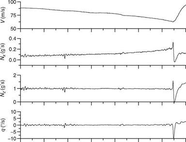
increases the bank angle. Since the nose drops due to increasing bank angle, he or she increases the AOA to maintain speed. This continues until the stall is reached or the g limit is reached. WUT is thus a descending spiral and will become tighter and steeper with increasing g. The aircraft will be in a steep nose down altitude with high bank angle. Subsequently, recovery to level flight is initiated. WUT should be performed with smooth increase in g and speed change should be minimal within 5-10 knots. Typical WUT maneuver flight-time histories are shown in Figure 7.11.
|
|
|
|
|
|
|
FIGURE 7.11 WUT performance maneuver time histories. |
Experience with flight data analysis has shown that no single maneuver, no matter how carefully performed and analyzed, can provide a definitive description of the aircraft motion over the envelope or even at a given flight condition in the envelope. Thus, it is always desirable to obtain data from several maneuvers at a single flight condition or a series of maneuvers as the flight condition changes. Often, two or more such maneuvers are analyzed to obtain one set of derivatives. This is more popularly known as multiple maneuver analysis.
7.8 SPECIFIC MANEUVERS FOR ROTORCRAFT
The rotorcraft, unlike fixed-wing aircraft, is more complex with the main rotor playing a key role in defining the overall dynamics of the flight vehicle. In rotorcraft, the off-axis responses cannot be ignored, as these are more often than not of similar magnitude as the on-axis responses. The interference effects from the main and tail rotors and the presence of vibrations at low frequencies further complicate matters. A variety of flight test maneuvers are therefore required to generate sufficient information to identify mathematical models with increased reliability for the rotor – craft. Normally, for identification of rotorcraft stability and control characteristics, inputs similar to those for the fixed-wing aircraft, e. g., doublets and 3-2-1-1, are applied to excite the longitudinal phugoid, pitch, and the lateral DR and spiral modes. Frequency sweep inputs are also used in good measure to generate flight data for rotorcraft system identification. An excellent insight into various aspects of rotorcraft identification is available [14].
For rotorcraft HQ testing, ADS-33 stipulates the mission task elements (MTE) to be performed [15,16]. These are treated as HQ tasks, and mission-oriented maneuvers are flown by pilots who assign subjective pilot ratings using the Cooper-Harper handling qualities rating (HQR) scale. The performance of a helicopter during piloted mission tasks ultimately defines its HQ. ADS-33E specifies nearly 23 MTEs. Execution of these mission maneuvers, which includes maneuvers like Hover, Landing, Hovering Turn, Pirouette, Vertical maneuver, Slalom, Sidestep, Deceleration to Dash, and Pullup/Pushover, generate a large amount of extremely valuable data for HQ evaluation. A typical rotorcraft flight maneuver is shown in Figure 7.12.
A few of the flight test maneuvers (ADS-33D) required to be performed on a rotorcraft to evaluate its HQ performance are described next [17]:
Hover: At a ground speed between 6 and 10 knots, at an altitude of less than 6.1 m, transit to hover, and maintain a precision hover for at least 30 s. This should be done in moderate wind from the most critical direction.
Hovering turn: At an altitude less than 6.1 m complete a 180° turn from a stabilized hover. With moderate wind from the most critical direction, perform the maneuver in both directions.
Bob-up/Bob-down: Bob-up to a defined reference altitude between 12.2 and 15.2 m from a stabilized hover at 3.05 m. Then stabilize for at least 2 s. Reestablish the
3.5 m stabilized hover by bob-down. Perform the maneuvers in moderate winds from the critical azimuth.
Acceleration/deceleration: From a stabilized hover rapidly increase power to nearly maximum and maintain altitude constant with pitch altitude. Accelerate to 50 knots at constant collective. After reaching the target speed, initiate deceleration by aggressively reducing power and holding altitude constant with pitch altitude, and then stabilize hover.
Sidestep: At a selected altitude below 9.15 m, starting from a stabilized hover, initiate a rapid and aggressive lateral translation, with a bank angle of at least 25°, while holding the altitude constant with power. After achieving a lateral velocity within 5 knots of maximum (or 45 knots), initiate deceleration to hover at constant altitude. Establish stabilized hover for 5 s and repeat in the opposite direction.
The above maneuvers are also specified with certain performance/desired parameters in ADS-33D. For example, in ‘‘hover,’’ the altitude should be maintained within ±0.61 m, the horizontal position should be within ±0.91 m and the pilot should be able to stabilize the helicopter in hover within 3 s.
The pilots need to pay extra attention to avoid exceeding the structural, aerodynamic, or control limits of the helicopter, while flying it to exploit its capability in the complete flight envelope. Piloted simulation evaluations should be made to investigate possible ways of alerting and aiding the pilot when close to transmission limits. Aggressive maneuvers can be flown in the simulator and the pilot reaction to various cues (like collective stick force feedback, aural cues, voice cues, and visual HUD cues) can be evaluated. The rotor rpm and rotor transmission limits should be monitored and evaluated. The active flight control approach can effectively eliminate uncommanded limit exceedance in high-aggression and large-amplitude maneuvers. Pilot cuing for impending limits can be based on the predictive capabilities of artificial neural networks (ANNs), which can be trained using helicopter flight test load survey database.