OPERATION OF THE MAIN ROTOR IN THE AXIAL FLOW REGIME
![]() During the rotation of the main rotor, a thrust force arises that creates lift and motion forces for the helicopter. The question of the origin of this thrust force is a basic question in the study of the main rotor operation. Several theories exist that explain the origin of the thrust force. We consider the physical aspects of two such theories.
During the rotation of the main rotor, a thrust force arises that creates lift and motion forces for the helicopter. The question of the origin of this thrust force is a basic question in the study of the main rotor operation. Several theories exist that explain the origin of the thrust force. We consider the physical aspects of two such theories.
§ 8. Impulsive Theory of an Ideal Rotor
In this theory an ideal rotor is considered — that is, a rotor that operates without losses. Such a rotor receives its energy from the engine, and all of it is transformed into work by displacement of the air mass along the axis of rotation.
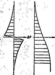
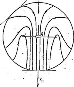
If the rotation of the rotor in the hovering regime is considered — that is, when there is no translational motion of the helicopter and its speed is zero — the air is attracted by the rotor from above and from the sides (rotor induced flow) and it is deflected downwards (Figure 14). A flow of air is established through the area swept out by the rotor. The parameters of this flow are characterized by the inflow velocity (the speed of the flow in the plane of rotation and the main rotor), by the downwash velocity of the flow of VD (the speed of the flow at a certain distance from the plane of rotation of the main rotor), by the increase of pressure in the flow ДР, and by the change of speed along the axis of rotation.
|

By deflecting the air downwards with a force T, the rotor receives a force from the air in the upward direction (action equals reaction). This force will he the thrust force of the rotor. But from mechanics, it is known that a force equals the product of the mass of a body times the acceleration that the body receives under the action of the force. Therefore,
![]() T = msa%
T = msa%
where m = mass of air per second, flowing through the area swept out by the rotor;
a = acceleration in the flow.
The mass of air per second is determined from the formula:
![]() ms = pFVt,
ms = pFVt,
where p = air density;
F = area swept out by the rotor;
= induced flow velocity (inflow velocity)
As is known, the acceleration is equal to the change of velocity in unit time, /17
![]() dV dt »
dV dt »
where dV = increase of flow velocity dt = time
If we take dt = 1 second, the acceleration a is numerically equal to the velocity increase, that is, a = dV.
Let us clarify the value of dV. Considering the operation of the rotor in the hovering regime, it is not difficult to see (Figure 14) that the air at a certain distance from the rotor is stationary — that is, its velocity relative to the rotor is zero.
Beneath the rotor, the air moves at the inflow velocity, which means that the velocity increase dV = V^. Then utilizing Formulas (1) and (2) we obtain
1 ■ "s> ■ Vd ■ рРЇЛ • (3>
In order to arrive at a final conclusion, it is necessary to ascertain the relationship between the inflow velocity V. and the downwash velocity V^. We use the law of conservation of momentum: ‘The impulse of a force equals
the increase of momentum’.
It will be recalled that the impulse of a force is the product of force and time. If the time dt = 1 second, then the impulse of the force numerically equals the force.
|
|
|
|
|
|
|
|
|
|
|
|
|
|
|
|
|
|
|
|
|
|
|
|
|
|
|
|
|
|
|
|

The conclusion is that the thrust force, developed by the main rotor, is proportional to the air density, the area swept out by th – rotor and induced velocity squared. –
In order to determine on what the induced velocity dc ^.nds, it is necessary to consider another theory that explains the ori* 1 of the thrust force of the main rotor.


