Our heavyweight helicopter equal in the world does not have
In Rostov started production of the most load-lifting rotary-wing car The Russian holding «Helicopt[...]

Everything about aircrafts and helicopters. News and events in aviation worldwide. Civil, transportation, military helicopters and airplanes.

Everything about aircrafts and helicopters. News and events in aviation worldwide. Civil, transportation, military helicopters and airplanes.

Everything about aircrafts and helicopters. News and events in aviation worldwide. Civil, transportation, military helicopters and airplanes.

Everything about aircrafts and helicopters. News and events in aviation worldwide. Civil, transportation, military helicopters and airplanes.


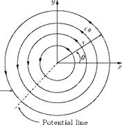
Vortex is a fluid flow in which the streamlines are concentric circles. The vortex motions encountered in practice may in general be classified as free vortex or potential vortex and forced vortex or flywheel vortex. The streamline pattern for a vortex may be represented as concentric circles, as shown in Figure 5.35.
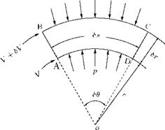
When a fluid flow is along a curved path, as in a vortex, the velocity of the fluid elements along any streamline will undergo a change due to its change of direction, irrespective of any change in magnitude of the fluid stream. Consider the streamtube shown in Figure 5.36.
As the fluid flows round the curve there will be a rate of change of velocity, that is, an acceleration, towards the curvature of the streamtube. The consequent rate of change of momentum of the fluid must be
|
Figure 5.35 Streamline pattern of a vortex. |
due to a force acting radially across the streamlines resulting from the difference of pressure between the sides BC and AD of the streamline element, as per Newton’s second law. The control volume ABCD in Figure 5.36 subtends an angle SO at the center of curvature O and has length Ss in the direction of flow. Let the thickness of ABCD perpendicular to the plane of diagram be ‘b’. For the streamline AD, the radius of curvature is r and that for BC is (r + Sr). The pressure and velocity at AD and BC are p, V, (p + Sp) and (V + SV), as shown in Figure 5.36. Thus, the change of pressure in the radial direction is Sp.
The change of velocity in the radial direction (as shown in the velocity diagram in Figure 5.36) is:
SV = VSO.
But SO = Ss/r. Thus, the radial change of velocity between AB and CD is:
Ss
SV = V—. r
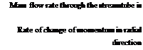 density x area x velocity p(b x Sr)V.
![]()
 |
(mass per unit time) x radial change of velocity VSs
(pbSr V)—- .
r
This rate of change of momentum is produced by the force due to the pressure difference between BC and AD of the control volume, given by:
F = [(p + Sp) – p]bSs. (5.61)
According to Newton’s second law, Equation (5.60) = Equation (5.61). Thus:
SpbSs = pbSrV zSs/r
P = pgh.
Therefore,
Sp = pgSh.
Substituting this into Equation (5.62), we get:
![]()
![]()
 |
Sh
PgT~ =
Sr
or
Sh _ V2 Sr gr
In the limit Sr ^ 0, this gives the rate of change of pressure head in the radial direction as:
The curved flow shown in Figure 5.36 will be possible only when there is a change of pressure head in a radial direction, as seen from Equation (5.63). However, since the velocity V along streamline AD is different from the velocity (V + SV) along BC, there will also be a change in the velocity head from one streamline to another. Such a change of velocity head in the radial direction is given by:
Rate of change of velocity head
in the radial direction = [(V + SV)2 — V2] /(2 g Sr)
VSV,
=——— (neglecting the products
g Sr
of small quantities)
V dV
=——– (as Sr ^ 0). (5.64)
g dr
For a planar flow (say in the horizontal plane), the changes in potential head is zero. Therefore, the change of total head H, that is, the total pressure energy per unit weight, in a radial direction, SH/Sr, is given by:
SH
— = change of pressure head + change of velocity head.
Sr
![]()
|
|
|
|
|
|
|
|