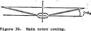
Main Rotor Cone of Revolution
When horizontal hinges are used, the rotating rotor forms a "cone of revolution". If the flapping angle is positive, as the main rotor turns the blades travel along the generator of a cone whose apex is located at the center of the hub. The plane passing through the rotating rotor blade tips is called the main rotor plane of rotation [tip path plane] (Figure 36).
The line passing through the center of the hub perpendicular to the tip path plane is called the coning axis. The main rotor thrust vector passes lies along the coning axis.
 If the blade flapping angle does not change azimuthally, the main rotor tip path plane is parallel to the hub rotation plane and the coning axis coincides with the main rotor hub axis. In this case the flapping angle 3 equals the coning angle a^. The coning angle is the angle a^ between the hub rotation plane and the generator of the cone of revolution. It varies from 0° to 10 – 12°.
The coning angle is larger, the larger the main rotor pitch. In – /53
crease of the pitch leads to increase of the blade thrust and moment about the horizontal hinge.
The main rotor cone of revolution is clearly visible if all the blades have the same flapping angle, i. e., there exists so-called co-conicity of the blades, absence of which leads to severe vibration of the main rotor. To obtain co-conicity it is necessary that the incidence angles of all the blades be the same. The technique for adjusting the rotor for blade tracking is given in the helicopter maintenance instructions.


