Constant temperature anemometer (CTA)
In the constant temperature anemometer the influence of the thermal inertia of the sensor is eliminated as the temperature of the wire is
constant whatever the velocity of the stream; the frequency limit of the instrument is therefore essentially determined by the electronic circuit.
1.6.1 Schematic of a CTA
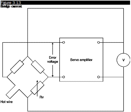
Figure 3.13 illustrates the basic pattern of a CTA: the wire is again in an arm of a Wheatstone bridge opposed to a variable resistor that adjusts the operating resistance, and hence the temperature of the hot wire; the output of the bridge is in this case connected to an amplifier whose output is in turn the supply voltage of the bridge. If the bridge is balanced, there is no potential difference across the diagonal. When the fluid speed increases, the sensor tends to cool and its resistance decreases; an imbalance of the bridge is generated that changes the input signal of the amplifier. The phase of the amplifier is such that the voltage reduction causes an increase of the output signal of the amplifier which increases the current in the sensor and then the temperature until it restores the balance of the bridge.
 |
Schematic of a CTA
If the amplifier has a sufficient gain, it is able to hold the input signal much closer to a balanced bridge, so any change in the resistance of the sensor is immediately corrected by an appropriate variation of the current. The output signal of the system at constant temperature is the output voltage of the amplifier, which, in turn, is the voltage required to ensure the required current through the sensor.
The physical reasoning confirms the trend of E = E(U) of Figure 3.7: if the speed increases ^ heat transfer between the sensor and the fluid increases ^ the sensor tends to cool and its electrical resistance to decrease ^ the amplifier sends more current in the wire to maintain the same resistance ^ the potential difference across the resistor increases.


