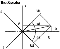
The X probe
The typical tool for determining both the unknown direction and absolute value of the velocity vector in a plane is the X-probe (Figure 3.19), consisting of two mutually perpendicular sensors, both at 45° with respect to the direction of the probe. The choice of these particular angles significantly simplifies the solution because the sine and cosine of 45° are equal and the sum of the angles formed by the velocity vector with the two wires is always 90°.
In the calibration phase, the probe is aligned with the stream and both wires are at 45° with respect to the direction of the velocity vector; the effective speed on each wire is
uiff=2^k )ui/
In the calibration phase, from the voltages measured on the two wires the corresponding values ucal1 and ucal2 are obtained. If in a test the speed is not aligned with the axis of the probe, the velocity components in the direction of the wires, u1 and u2 are derived from the following equations obtained by applying Equation (3.16) to the special case of the X-probe,
 |
Figure 3.19
Probe syst.: x, у Wire syst.: 1,2
U = U1cosa1 + U2cosa2 V = U1sina1 – l^sinc^
 |
in which case, since the two wires are mutually orthogonal, the component parallel to a wire is orthogonal to the other:
Finally, the components of the velocity vector in the direction of the probe and in the direction normal to it, u and v, respectively, are given by:
V2 ( + ) V2 ( )
U = — (l + U2 ) v = ~ (U1 – U2 )


