Thrust and Power Required. for Horizontal Flight

In horizontal flight the thrust force vector is tilted forward from the vertical and to the side in the direction of the retreating blade.
mation of the side force S = T,
s t. r
and the result of the forward tilt of the thrust force vector is the formation of the propulsive force P = T sin у which pulls the helicopter forward,
overcoming the parasite drag. We recall that helicopter parasite drag is the resistance of all the nonlifting parts (other than the main rotor).
The projection of the thrust force on the vertical yields the lift force Y = T cos y. Therefore, to generate the lift and propulsive forces it is necessary to have the thrust force T^, which can be found from the force diagram (see Figure 59).
![]() (26)
(26)
The thrust required for horizontal helicopter flight depends on its weight and parasite drag, which can be found from the formula
par
The parasite drag coefficient depends basically on the shape and attitude
of the fuselage, and also on the condition of its surface. The parasite drag
2
is proportional to the flight velocity squared, i. e., X ^ = f (V ).
With increase of the horizontal flight velocity the thrust required increases.
In horizontal flight there is a change not only of the magnitude of the thrust required, but also of its direction, i. e., the angle у of deflection of the thrust force vector from the vertical. Increase of the angle у is necessary in order to increase the propulsive force P while leaving the lift force Y unchanged.
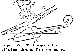
Tilt of the thrust force vector and increase of the angle are accomplished in three ways:
1) by deflecting the main rotor cone of revolution axis forward;
2) by tilting the helicopter forward;
3) by establishing the main rotor shaft at some angle g relative to the perpendicular to the fuselage structural axis (the line running along the fuselage), Figure 60.
Tilting the cone axis forward through the angle Г| is accomplished by deflecting the helicopter control stick forward. The main rotor cone axis tilts in the same direction in which the stick is deflected.
Tilting the entire helicopter through the angle 0^ (pitch angle) is accomplished by deflecting the control stick forward. The main rotor shaft
installation angle relative to the helicopter structural axis always remains the same.
 Thus, the thrust force vector forward tilt angle will be equal to
the sum of the angles Л» 3. The larger the angle y, the larger the propulsive force P, and the higher the helicopter speed.
The work which must be supplied to the main rotor shaft per unit time is called the power required for

helicopter horizontal flight. The power required is made up of three parts: [1] [2] [3]
Using (26a), we find the power required for motion of the Mi-1 helicopter (G = 2200 kgf, H = 0).
(continued)
|
|
||
|
|||
|
|||
|
|||
|
|||
![]()
These values make it possible to plot a graph of the variation with
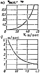
flight speed of the power required for motion of the helicopter (Figure 61a).
2
Since N and the parasite drag X = f (V ), the motion power required mot _ par
N = f (v) and increases more sharply with increase of the flight speed, mot
The average induced velocity for the main rotor of the Mi-1 helicopter decreases with increase of the horizontal flight speed (Figure 61b).
Using this figure and the Formula (27), we calculate the induced power,
i. e., the power expended in creating the helicopter lift force
 Nt = -2-^- = 245 hP; m/sec: « -22(^,–5- = 147 hp;
– , дг 2:;00-!>,6 oc
m/sec; N і ——- ycj — OO hp1
From these results we can plot the induced power as a function of flight speed (Figure 61c) .
The reduction of the induced power with increase of the flight speed is explained by the fact that the rotor interacts with a larger mass of air ; therefore, less downwash is required to create a lift force equal to the /92
ч N, hp c) pr’ F
 11:
11:
cO
ад
ад із
V. m/sec
О 7.0 ад и
‘Л m/sec ‘•< m/sec
Figure 61. Power components versus flight speed.
helicopter weight. The power expended in overcoming profile drag increases with increase of the flight speed (Figure 61d). The increase of the profile power is explained by the increase of the air friction forces in the blade boundary layer with increase of the flow velocity over the blades. In the forward flight regime the flow relative velocity increases for the advancing blades (V7 = U + KsirHi-‘ > while it decreases for the retreating blades
— V Sini^), but since X = f (W^) the drag of the advancing blade increases more rapidly than the drag of the retreating blade decreases. After calculating the component parts of the power required, we find the power required for horizontal flight of the Mi-1 helicopter
V = 10 m/sec; = 4 + 147+ 140 = 291 hp;
V = 30 m/sec; Nh = 37 + 62 + 160 = 259 hp;
V = 50 m/sec; Nh = 153 + 42 + 180 = 375 hp.
Using these values, we plot the power required for horizontal flight as a function of the flight speed for the Mi-1 helicopter(H = 0; G = 2200 kgf)
(Figure 62). We see from this figure that with increase of the velocity from zero to 80 km/hr the power required for horizontal flight decreases. The speed for which the power required for horizontal flight is minimal is called the helicopter’s economical speed.


