Flapping Motion
To examine the flapping motion more fully we assume, unless otherwise stated, that the flapping hinge is on the axis of rotation. This simplifies the considerations without hiding anything of significance.
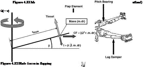
Referring to Figure 4.12, the flapping takes place under conditions of dynamic equilibrium, about the hinge, between the aerodynamic lift (the external forcing function), the centrifugal
force (the ‘spring’ or restraining force) and the blade inertia. (The aerodynamic lift varies as the blade flapping responds in a manner which acts as a damper.) In other words, the once-per-cycle oscillatory motion is that of a dynamic system in resonance. The flapping moment equation is seen to be:

![]()
![]()
 |
(4.3)
We shall return to this equation later.
The centrifugal force supplies, by far, the largest force acting on the blade and it creates the moment which provides an essential stability to the flapping motion – essentially it acts as a spring. The degree of stability is highest in the hover condition (where the flapping angle is constant) and decreases as the advance ratio increases. Bramwell’s consideration of the flapping equation (p. 153ff.) leads in effect to the conclusion that the motion is dynamically stable for all realistic values of ц.
For normal forward flight, the maximum flapping velocities (b) occur where the resultant air velocity is at its highest and lowest, that is at 90° and 270° azimuth. Maximum displacements occur 90° later, that is at 180° (upwards) and 0° (downwards). As will be seen, the flapping has a natural frequency very close to that of the rotor speed. It is therefore close to a resonant condition which will give a phase delay of near 90° (exactly 90° for a zero hinge offset). While it is near resonance, the aerodynamics provides the damping to keep the responses under control. As already outlined, these displacements mean that the plane of rotation of the blade tips, the tip-path plane (TPP), is tilted backwards relative to the plane normal to the rotor shaft, the shaft normal plane (SNP).
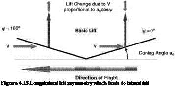
In hover, the blades cone upwards at a constant angle to the SNP, known as the coning angle, usually denoted by a0. Its existence has an additional effect on the orientation of the TPP during rotation in forward flight.
Figure 4.13 shows that, because of the coning angle, the flight velocity Vhas a lift-increasing effect on a blade at 180° (the forward blade) and a lift-decreasing effect on a blade at 0° (the rearward blade). This asymmetry in lift is, we see, at 90° to the side-to-side asymmetry discussed earlier: its effect is to tilt the TPP laterally and since the point of lowest tilt follows 90° behind the point of lowest lift, the TPP is tilted downwards on the advancing side which, with, a rotor rotating anticlockwise from above, is to the right. The coning and disc tilt angles are normally no more than a few degrees.
Since in any steady state of the rotor the flapping motion is periodic, the flapping angle can be expressed in the form of a Fourier series:
b = a0—aj cos C—bi sin C—a2 cos 2ф—Ь2 sin 2C… (4-4)
Textbooks vary both in the symbols used and in the sign convention adopted. The use of negative signs for the harmonic terms is a throwback to the emergence of the autogyro where a rearward disc tilt was the norm, and where the coefficients aj and Ь have positive values. For most purposes the series can be limited to the constant and first harmonic terms – which represent the coned rotor and the disc tilt – thus:
![]()
 |
b = a0—a cos C—Ьі sin C
This form will be used in the aerodynamic analysis of the next chapter. For the moment we note that:
• a0 is the coning angle;
• a1 is the angle of backward disc tilt;
• b1 is the angle of sideways disc tilt (advancing side down).
The inclusion of second or higher harmonic terms would represent perturbations about the TPP (in-plane weaving) but any such is of secondary importance only.
Timewise derivatives of b will be needed in the later analysis: using the fact that the rotational speed Q is d^/dt, these are:
|
b = Q-jC = Q(ai sin C—bj cos C) |
(4.6) |
|
о d2 b о € = Q2—2 = Q2(a1 cos C + b1 sin C) dC |
(4.7) |
The transformation to b as a function of C, the blade azimuth, makes the solutions more informative and therefore useful. It also has the benefit of causing many scaling terms to cancel out.


