Rotor Aerodynamics in Forward Flight
The aerodynamic situation in forward flight is complex. Numerical methods have largely taken over the task of evaluation but an analytical treatment, using simplifying assumptions, is valuable for providing a basic understanding of rotor behaviour. Such a treatment is the subject of this present chapter. The mechanisms of the previous chapter affect essentially the details of blade element theory. Before turning to that, however, it is useful to examine briefly what can be made of momentum theory, which as has been said is principally a theory for hover and axial flight; also it may be asked to what situations one is led in considering a more detailed wake analysis under forward flight conditions.
5.1 Momentum Theory
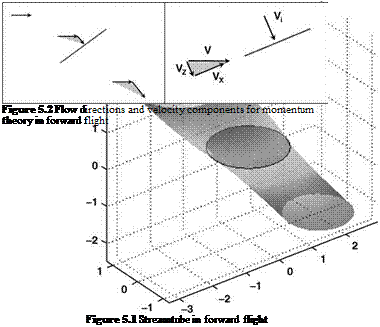
As the rotor begins to attain forward flight speed, the velocity of the air entering the rotor will increase as the forward flight speed combines with the sum of the induced velocity and any axial flight speed. In addition, it will approach the rotor disc at an inclined angle, hence any development of the actuator disc theory to include forward flight must address these issues. The type of streamtube shape seen in forward flight with an actuator disc is shown in Figure 5.1.
The modelling of the actuator disc theory into forward flight was addressed by Glauert [1] who devised a scheme which was based on the following:
• The concept of the streamtube is adopted.
• The area presented to the airflow for mass flow calculations is the whole disc area. This ensures the method is consistent with lifting line theory for a rectangular wing. In this case, the area for momentum calculations is a circle with the wing as diameter.
• The induced velocity is normal to the disc plane.
• The induced velocity in the far wake is twice that at the rotor disc – as in axial flight – and is also normal to the disc plane.
Basic Helicopter Aerodynamics, Third Edition. John Seddon and Simon Newman. © 2011 John Wiley & Sons, Ltd. Published 2011 by John Wiley & Sons, Ltd.
The velocities of the air through the streamtube are shown in Figure 5.2.
Expressing all velocities relative to the rotor:
• Far upstream, the airflow is horizontal.
• At the rotor disc, the induced velocity is added (vectorially) to the forward flight velocity.
• Far downstream, twice the induced velocity is added (vectorially) to the forward flight velocity.
With the notation of Figure 5.2, and noting the second statement of the scheme, the mass flow into the rotor disc is given by:
![]()
 |
pAy/vX+(VZ+Vi )2
|
|
|
|
|
|
|
|
|
|
|
|
|
|
|
|
|
|
|
|
 |
|
|
|
|
|
 |
|
|
|
![]()
which can be recast as:
|
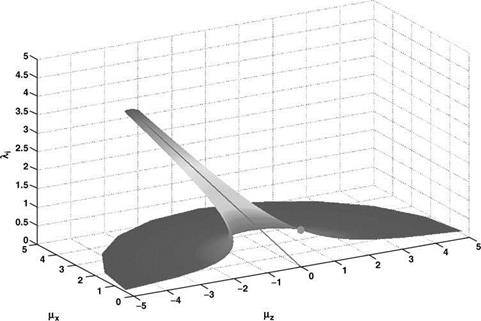
Figure 5.3 Solution surface for actuator disc theory |
Hence, for a given value of downwash, that is in a given plane parallel to the base (mX, mZ) plane, Equation 5.8 defines a circle:
Centre ) (—mz, 0)
P H – 1 (5-9)
Radius
li
The surface defined by (5.8) is shown in Figure 5.3.
The figure shows both the basic shape of axial flight and the effect of forward flight. As the forward flight velocity increases, the problems of moderate descent rate diminish and eventually disappear. The figure shows the mathematical results of the theory, but in reality the effect of forward speed is of providing a second mechanism for the rotor to clear the vorticity forming at the rotor disc.
The usual situation is of wanting to determine the value of the downwash from the advance ratio components and the rotor thrust. This means solving Equation 5.7, if we assume that we are working with normalized values of velocity.
This can be solved in two ways. Firstly it can be viewed as an iterative scheme, where an initial guess at a value of li is substituted into the right-hand side of (5.7) which gives a revised value. This has been shown to work well for high speeds where the mX term dominates. However, at low speeds, the calculation can take a large number of iterations to converge on a value to a sensible degree of accuracy. In hover, the routine will never converge – unless the
correct solution is used at the outset. A modification to the method was devised by Hansford who re-expressed (5.7) as:
|
|
|
|||
![]()
This is now the solution for the root of a function of (1i) that is equal to zero – and invoking Newton-Raphson. This gives the following iterative scheme:
![]()
 (5.11)
The calculation is more complicated but convergence is achieved efficiently over the entire speed range.
Equation 5.10 can be squared and rearranged to give:
This is a quartic which gives four solutions. These comprise a complex conjugate pair, which can be discarded. The two real solutions are of opposite sign. As the induced velocity is always taken to be positive, the negative value can also be discarded. Hence the real positive solution is the one that should be used. This calculation has been performed over a range of values for mx and mz and the results are shown in Figure 5.4.


