Descending Forward Flight
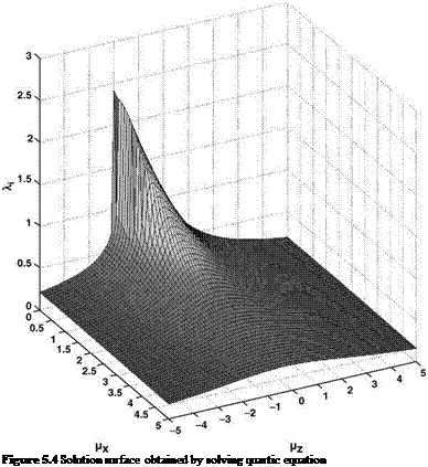
As can be seen in Figure 5.4, the majority of the surface is the same as Figure 5.3; however, the main difference is in the vortex ring state region of moderate descent with low to zero forward flight speed. Here the solution experiences a rapid jump in value – which, in fact, is not totally incorrect. Perhaps the most significant error in character is the fact that a steady value of induced velocity is indicated – the theory defines this – but, as already discussed, this is not the case in reality. We therefore need to define a region dividing those flight conditions which can be handled sensibly by actuator disc theory (ADT) and those which require a different approach. This requires the introduction of a vortex ring state boundary. This will be governed by the ability of the rotor to clear the vorticity which is being generated at the rotor disc.
So if we consider the overall advance ratio:
then that is the total normalized velocity through the rotor disc and will be the main influence in carrying the vorticity away. Work conducted on this topic by Newman et al. [2] defined this velocity to have a critical value, whence the boundary perimeter is defined by:
![]()
 |
mCRIT — J mX2 + (^Z + ^i)
This formula assumes that the forward and vertical velocities are completely efficient in disposing of this vorticity. However, consultation of the flow visualization of Drees [3] by Perry [4], showed that the forward velocity component does not operate with perfect efficiency. In addition, Brand [5] proposed a similar adjustment to the total vertical component. The revised boundary definition now becomes:
 |
|||
which can be rearranged to give:
If we now substitute (5.16) in (5.7) we obtain:
k2
yW2 (k2 ki) + mcRiT2
Hence, for a given value of /tCRIT and "x the values of mz and 1i, the boundary point, can be defined using (5.16) and (5.17).
Using the following values:
mcRiT — 0.74
k1 — 0.65 (5.18)
k2 — 0.9
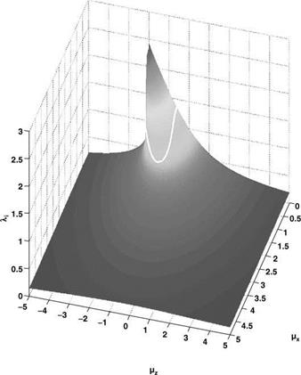
the boundary is as shown in Figure 5.5.
As can be seen, the boundary hangs – like a necklace – around the area of concern. Having established the boundary, outside of which ADT can be sensibly used, the situation within the boundary needs comment. This is the region where the flow is dominated by vorticity and where a much more detailed theory needs to be used. Alternatively, which was the way initially used, experimental data can be introduced. Both experiment and more detailed analysis (see e. g. Bramwell’s Chapter 4) confirm that the Glauert proposal works well.
In practice the induced velocity cannot be expected to be constant over the area of the disc. Standard aerofoil theory would suggest an upwash at the leading edge and a greater-than – mean downwash at the trailing edge. To allow for a variation of this kind, Glauert proposed a second formula:
Vi(x, C) — Vi0(1+Ex cos C) (5.19)
where Vio is the value at the centre, taken to be that given by (5.3), x is the non-dimensional radius from the centre and C is the azimuth angle. If the constant E is chosen to be greater than 1.0 (typically 1.2), the formula gives a negative value, that is an upwash, at the leading edge (C — 180°). Equation 5.19 is often used as an input to numerical methods.
|
Figure 5.5 Solution surface and proposed VRS boundary |
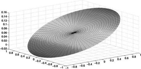
A plot of this profile, with E having the value 1.2, is shown in Figure 5.6.
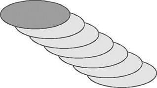
The plot is an inclined plane; note the negative values at the front of the disc. A justification for this downwash model can be found in examining a more detailed model using vortex rings, if they are positioned in an inclined stack, as shown in Figure 5.7.
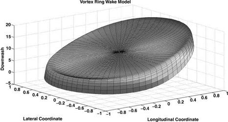
The resulting downwash variation is shown in Figure 5.8. As can be seen, the planar nature is shown within the central part of the disc and a negative value is predicted at the front of the disc. The ridge of the distribution in a region close to the disc edge is a local effect attributed to the vortex ring closest to the rotor disc.
More elaborate treatments of the non-uniform induced velocity in forward flight have been devised, among which one of the foremost is the method of Mangler and Squire [6]. Described at length by Bramwell (p. 127ff.), this method has shown satisfactory agreement with controlled experiments and is stated to be very useful in rotor calculations.
Reverting to the Glauert formula for uniform induced velocity, Equation 5.3, the induced power is:
T 2
2pA^JvX+(Vz+Vi )2
|
|
 |
which at normal forward flight speeds becomes approximately:
![]() T 2
T 2
2pAV
![]() = T (T ) —
= T (T ) —
A 2rV
Tw = 2pV
that is, directly proportional to the disc loading w.
|
|
Figure 5.8 Vortex ring geometry, downwash variation |
In non-dimensional terms the first equality of (5.20) is simply:
CPi = li • Ct (5.22)
where 1i is Vi/OR. It will be useful for the forward flight case to adopt a suffix ‘i’ for that part of the total induced flow which is due to the thrust-dependent induced velocity Vi, as distinct from a part due to the forward velocity V.
As with hover, a practical approximation to allow for the effect of non-uniformity in Vi and other smaller correction factors is obtained by applying an empirical factor k such that:
Cpi = ki • li • Ct (5.23)
The value of ki in forward flight is somewhat higher than that in hover, say 1.20 compared with the formerly suggested 1.15 (Section 3.6). Countering this, however, the induced velocity is seen in Figure 5.5 to become quite small even at moderate forward speeds: it will duly emerge that CPi is then much smaller than other components of the total power requirement.


