Elastic Surface Motion Concept
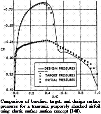
There arc many reliable and relatively fast 3-D flow-field analysis codes in existence It would be highly economical to utilize these analysis codes in an inverse shape design process. This would require development of a short and simple design code that can utilize any of the existing flow-field analysis codes as a large, exchangeable subroutine One very simple method for developing such a design code is based on utilizing an elastic membrane as a mathematical model. This concept treating those parts of the surface of the aerodynamic flight vehicle that are desired to have a specified surface pressure distribution as a membrane loaded with unsteady point-forces. ACp. that arc proportional to the local difference between the computed and the specified coefficient of surface pressure. Under such an unsteady load the membrane will iteratively deform until it assumes a steady position that experiences zero forcing function at each of ihc membrane points. Since this is a general non-physical concept for modeling die unsteady damped motion of the 3-D aerodynamic surface, any analytical expression governing damped motion of a continuous surface will suffice. Garabedian and McFaddcn [147] suggested a stmplc second-order linear partial differential equation as such a model where ACp is proportional to the local surface slopes and curvatures.
Ал + P, • Д-Дл + P2 * + P, • -^-A/i + P4 = p5 ACp (72)
fir Э y‘
Here, the unknowns arc the local normal surface displacements, An. If the surface grid point in question is on the upper surface. = 1.0. if on the lower surface. (i5 = -1.0 The remain-
 |
ing coefficients through P4 are user-specified quantities that can accelerate the approach to a steady state. This partial differential equation can be discretized using finite difference representations for the partial derivatives. This leads to one pcnta-diagonal system or a sequence of two three-diagonal systems of algebraic equations that can readily be solved for the unknown normal surface modifications. Дп,. This simple technique was successfully used to design isolated 3-D transonic supercritical wings [148] with a 3-D full potential code (Figure 71) as the flow analysis module. A simplified version of this concept (with Дг instead of Дп) was used to design engine nacelles and wing-body configurations [ 149). The initial guess for the shape of a 3-D body does not have to be close to the final configuration for this method to work. Although requiring only 30-100 calls to a flow-field analysis code when using a panel code or a full potential equation code, the stiffness of the iterative matrix in the present formulation of the elastic membrane concept increases rapidly with the non-linearity of the flow-field analysis code used. This means that when using Euler or Navicr-Stokcs flow-field analysis code we will need between two and three orders of magnitude more calls to the flow-field analysis code than when using a simple linear panel code. For example, a two-dimensional airfoil shape inverse design with this method utilizing a Navicr-Stokcs flow analysis code may require over ten thousand calls to the Navicr-Stokes code [1501.
Figure 71


