Analysis
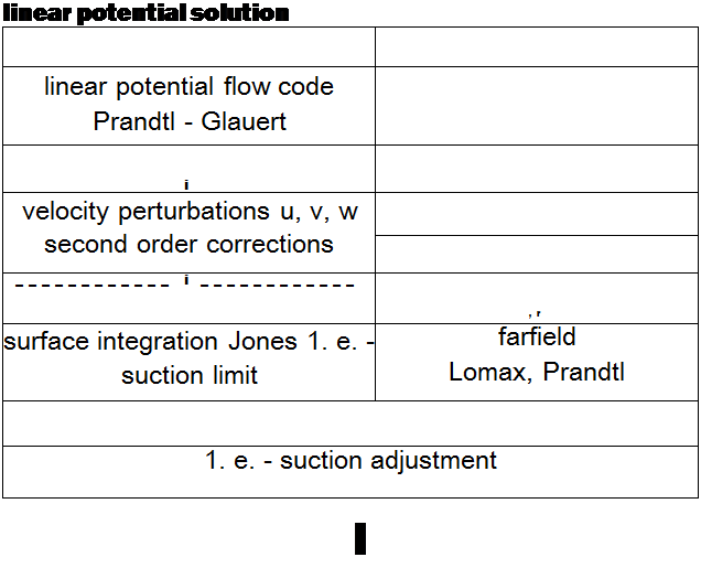
A linear panel code with real flow corrections was used to analyze drag for 3D supersonic wing body configurations. This analysis code was developed by the author from Woodward’s wing – body code (3551. anti solves the linear Prandtl-Glaucrt equation for a thin panel geometry. The power plants are modeled as stream tubes that displace ambient fluid and therefore cause wave drag. Friction is calculated stnpwise over the cursed geometry assuming a fully turbulent boundary layer. No effort was made to couple the boundary layer equation to the potential flow pressure distribution. Potential drag is calculated with surface integration and a calculated value of the leading edge thrust. The correct leading edge thrust is found by combining the far-ficld drag as calculated by the Lomax supersonic area rule (345) and Trefftz-plane integration. The leading edge suction is then corrected for real flow effects using the method of Carlson (335|. The Toren – bcck quasi-empiric method (348] is used to model the effect of flap deflection. An overview of this method is given in Figure 91. A more detailed description can be found in the author’s thesis
(350) .
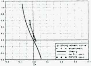
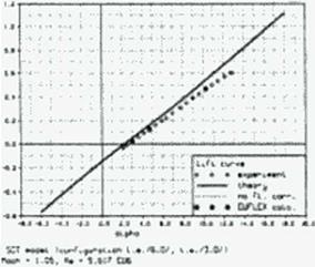
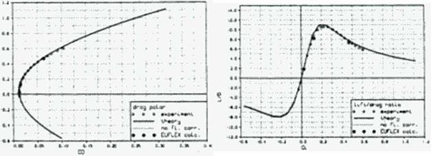
The forces and moments calculated with this method compare well with values measured from the NASA Ames Oblique Wing development program, a generic SCT, a generic fighter and the Munroe NASA arrow wing tests. Figure 92 shows the calculated and measured forces and moments for a generic SCT with 12 degrees leading and 3 degrees trailing edge flap deflection at Mach 1.05—a difficult case for panel calculations. Our method, which was applied to a panel half-model with a resolution of no more than 120 panels, look one second per flow point on our workstations. The Euler method EUFLEX (343) with a decoupled boundary layer calculation took about an hour on a Cray.


 |
|
|
forces, moments
Figure 91 A panel method with flow corrections to evaluate forces.
|
|
|
|
|
|
|
|
|


