
Our heavyweight helicopter equal in the world does not have
In Rostov started production of the most load-lifting rotary-wing car The Russian holding «Helicopt[...]

Everything about aircrafts and helicopters. News and events in aviation worldwide. Civil, transportation, military helicopters and airplanes.

Everything about aircrafts and helicopters. News and events in aviation worldwide. Civil, transportation, military helicopters and airplanes.

Everything about aircrafts and helicopters. News and events in aviation worldwide. Civil, transportation, military helicopters and airplanes.

Everything about aircrafts and helicopters. News and events in aviation worldwide. Civil, transportation, military helicopters and airplanes.


16.5.1 Oblique Flying Wing
The design presented here is part of a MIDAS design cycle described previously in paper (354). The global design was optimized for a Mach number of 1.6 and therefore had a fixed wing plan – form. sweep and thickness distribution. In the global model a preliminary wing planform was determined. and the assumption was made that there existed a thickness and camber distribution which would produce a lift-to-drag ratio of 11 at Mach 1.6 with a cruise lift coefficient of 0.10. This globally optimized aircraft had a span of 120m and a 14.2 m w ide center section chord that was 2.7 m thick. It was assumed that near elliptic off design load distributions could be obtained by unsweeping the wing at lower Mach numbers and deflecting the trailing edge suitably. It is therefore acceptable to just optimize the aircraft with respect to cruise drag while keeping the span, and the center section (passenger cabin) dimensions the same.
The objective of the aerodynamic shape optimization is to find the best aerodynamic shape (minimum drag) under these constraints and compare it with the value projected by the global model. In this detailed geometric shape optimization we must therefore derive a shape that does not interfere with and enables the assumptions of the multidisciplinary global optimum The global optimum was defined with respect to total operating costs.
The design variables were:
1. Angle of attack a and continuously varying section incidences expressed as a Taylor series afe/ у ■* CjV2 *cj y*+c4 y4)
2. Wing bend expressed as a Taylor scries zfc/y-fcjy^+cjУ*+с4у4). The z curvature produces an anti-symmetric twist distribution when the wing is obliquely swept.
3. Outboard wing chord(y) at 25. 40 and 60 m (tip). The wing chord distribution is assumed to be symmetric between left and right side (all у cuts arc mirrored) and is assumed to vary linearly between the defined у cuts.
4. cruise sweep A was variable but limited to 70 degrees.
5. Wing shape functions expressed as fourth order Taylor scries Y; {stfcіУ+С})^+c+c4y4}
ТІю constraints were:
1. The cruise lift coefficient C{ <0.1
2. No pitching and rolling moments around 32 root chord c. g.
3. Normal Mach numbers on the wing greater than 0.4 to prevent trailing edge separation. Normal Mach numbers not greater than 1.1 to prevent strong nonlinear effects that are not accounted for in the linear potential code.
4. Aisles higher than 2.2 m. cabin doors higher than 1.95 m. cargo hold higher than 1.7 m and underfloor crash zone higher than 50 cm. An extra 10 cm is reserved on each side of the geometry for structural reinforcements This corresponds to current Airbus standards. Including structural dimensions this resulted in a maximum external thickness of 2.70 m.
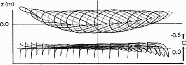
Figure 93 shows the optimized design. Remarkable is the wing bend that the optimizer applied to create an elliptic lift distribution Wing bend has the same effect as twist, but as the wing unsweeps, bend docs not produce an asymmetric loading. In comparison to earlier designs by the author based on inverse methods (350) the current designs are much more symmetric and have flatter pressure distributions. The current design also achieves near the minimum theoretical drag at supersonic flow. It achieved the projected lift-to-drag ratio of 11 very accurately and therefore validated the overall approach. The kink in the 3rd section from the left is not caused by the shape functions, but by the kink in the planform. The sections and pressure distributions shown in Figure 93 are streamwisc slices of the oblique flying wing.
50 I M=1.6CL=0.1
 |
-60.0 o. o 6o. o
x Cm)
Figure 93 Optimized Oblique Flying Wing
