MIDAS: A Design Process
How doc we best achieve flexibility and efficiency in our design process while effectively using the talent available to the organization? Figure % shows our solution called Multi-Disciplinary Integration of Deutsche Airbus Specialists.
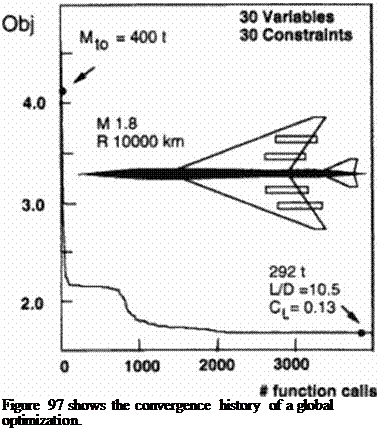
On the highest level there exists a global model of aircraft performance and economy as a function of its specification and a set of design variables. The analysis routines in the global model are supplied by the departments who have final responsibility. In about an hour numerical optimization of these design variables will prov ide an estimate of the aircraft’s main characteristics and geometric dimensions.
specifi
Abstraction
principal paramete S. AR. M, CL
model maintenance
interaction
detail
experiment
Global Model
 |
Figure 97 Global optimization
Alter the optimized design is finished it is critically evaluated by the specialists. Once the decision is made to develop a design further, the departments verify the pertinent results of the global optimization in greater detail This verification includes the design of a more detailed geometry on the basis of the global optimization output, much like putting the flesh on a skeleton. The values predicted by this intermediate model are compared to those for the global model and if necessary the global model is corrected and the process is repeated. Typically, no more than two iterations are required. In some cases the intermediate design level is also automated resulting in a closed global-intermediate loop In this case only computational limitations prevent further integration. Note, that at the intermediate design level, within each department a new group of parameters must be optimized which justify the simplifying assumptions made at the global level. For instance in the global aerodynamic model, the xssumption is made that there exists a wing camber distribution that has near minimum potential drag for a given plan – form. The wing planfonn is optimized during the global optimization cycle. At the intermediate level, the camber (represented by shape functions) is then optimized to achieve minimum lift dependent wave drag for this planform and lift. Finally the resultant ratios of the achieved minimum lift dependent wave drag to the global theoretical minimum is used as a correction factor in the next global optimization. Figure 98 shows the convergence history of the intermediate aerodynamic optimization for several optimizers.
Figure 98 Intermediate aerodynamic optimization
If this ratio exceeds an allowed percentage, the model itself should be corrected The intermediate model should not introduce parameters that conflict with the global model variables. A detailed description of the intermediate model can be found in references (37|) and I373).
To date we have used this method to obtain a number of SCT configurations. The configurations presented here have many of the features of these proprietary designs, but do not present the actual configurations.


