Lift Enhancement by Wing Flexibility
delayed burst of the leading-edge vortex. Aerodynamic and inertial forces applied on a flapping wing can result in passive wing deformations, which are likely responsible for stabilizing and hence delaying the breakdown of the LEV/TiV during wing translation. As illustrated in Figure 4.55c, both flexible and rigid wings show a similar high peak of vertical force immediately after the wing turns to decelerate.
This is because the LEV keeps growing and attaching coherently onto the wing surface, even after the LEV breaks down with the TV shedding off the wing surface [225] [ 388]. However, there exists a pronounced discrepancy at the early downstroke where the flexible wing obviously creates more vertical forces than the rigid wing (Fig. 4.55c). At instance A, a stronger LEV as a portion of a horseshoe vortex is observed near the wingtip of the flexible wing, which grows rapidly over instances of B, C, and D, resulting in a larger and stronger negative pressure region on the wing surface (Fig. 4.55e). Apparently, the spanwise bending of the flexible wing induced during pronation creates this LEV at an earlier timing than in the rigid wing (Fig. 4.56a), which leads to a fast and steep increase in vertical force at A-B (Fig. 4.55c). The LEV then keeps growing for a while up to instance D before approaching the middle down – and upstroke. During the interval, although the inertial force becomes very small (Fig. 4.56i), the spanwise bending and twist and hence the angular velocities show significant variations near the wingtip (B and C; the marked circle in Figure 4.55b). These wing deformations very likely stabilize the LEV and hence result in a delayed burst (breakdown) at D compared with that of the rigid wing at C (Fig. 4.55e). This delayed burst even further influences the development of the LEV after the breakdown, and subsequently the flexible wing reaches a higher force peak than in the rigid wing (Fig. 4.55c). Furthermore, a nose-down twist (Figs. 4.55 and 4.56) can result in a pronounced direction change of the spanwise wing cross-sections, and hence in the direction of force vectors (Fig. 4.55) and the downwashes.
phase advance and angular velocity increases. As seen in Figure 4.55a, the timing of wing twist is adjusted in a passive but adaptive way to advance the phase of wing rotation. This phenomenon is also observed in 2D studies regarding chord – wise flexibility. Moreover, the spanwise flexibility can cause a spanwise bending and hence delays the timing of stroke reversal at the wingtip. Therefore appropriate combination of the chord – and spanwise deformation leads to a relative phase advance of rotation in flexible wings, which can strengthen the vortex ring and the downwash, as well as the rotational circulation, while modifying the wing attitude to benefit from the wake capture [201].
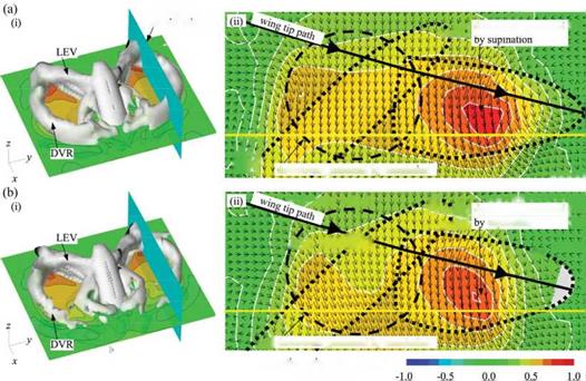
In addition, the wing deformations seem to lead to increasing angular velocities of positional and feathering angles, mostly in the distal area of flapping wings (Fig. 4.55), which can augment the circulation around insect wings [291]. Obviously, the relative phase advance and the angular velocity increase correspond with a larger vertical force (Fig. 4.55), rather than that of the rigid wing during wing rotation. Hence the spanwise bending is responsible for most vertical forces produced immediately before stroke reversal (Fig. 4.55). Furthermore, the rigid wing model with the deformed wing kinematics prescribed (Fig. 4.55) does provide concrete evidence that not only the three-dimensional wing configuration but also the variation in wing kinematics can enhance the aerodynamic force production. In relation to the downwash and the force production, the stronger downward flow (Fig. 4.57) is created in a timely fashion when the wing experiences a rapid stroke reversal where larger forces are created (Fig. 4.55), which was also confirmed experimentally by Mountcastle and Daniel [473].
As noted by Nakata and Liu [523], a rigid wing model with the prescribed wingtip kinematics can create a large vertical aerodynamic force comparable with that of the

 f % t * ** *■ * < < < * * ^
і/ ф Ф ■l Ф downwash generated |Я
7 lYi ^ ^ suPination v v
![]()
vr vv
£ і downwash generated by translation
Non-dimensional downward
flow velocity
Figure 4.57. Wake structures generated at downstroke about (a) flexible and (b) rigid wings.
(i) Iso-vorticity surface is plotted with a magnitude of 1.5; downwash at a horizontal plane and
(ii) at a cutting plane of 0.6 R from the wing root is visualized in terms of velocity vectors and downward velocity contours. Note that DVR stands for the downstroke vortex ring. From Nakata and Liu [523].
flexible wing; however, this force results in a significant drop in aerodynamic efficiency of 39.8 percent. Furthermore, the efficiency enhancement attained by flexible wings requires more input power. This is because the wing kinematics at the wingtip is modified passively – but favorably – due to the elastic wing deformation, albeit with an input of relatively inefficient wing kinematics at the wing base. Note that the wing base in hovering has low velocity and is ineffective for aerodynamic force production. This suggests that there may be an optimal distribution of wing kinematics between the wing base and wingtip, which should be more efficient in creating vertical aerodynamic forces; see also the discussion in Section 4.5. This points to the importance of the dynamic spanwise distribution of wing kinematics in enhancing aerodynamic efficiency and thus confirms that the elastic wing deformation is an effective way to achieve higher aerodynamic performance in insect flapping flight.


