AEROFOIL SELECTION
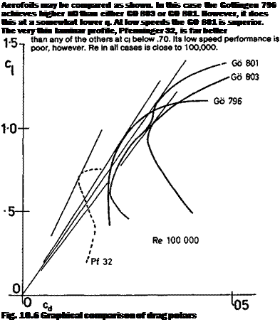
For aerofoil selection purposes it is useful to know that the best lift to drag ratio of a profile may be estimated direcdy from the drag curves as reproduced here. This is done by drawing a tangent from the origin or zero point of the drag graph to touch the plotted drag curve at a tangent (the curve appropriate to the Re of the model should be used). This is illustrated (Fig. 10.6). Tangential lines to the drag curves or ‘polars’ of several aerofoils are compared. The steeper the slope of the tangent, the higher the 1/d ratio of the profile. The application of the method is limited to tests at identical, or at least similar, Re. In a similar way, values of the profile power factor may be worked out and plotted as shown in Appendix 1 and Figure 10.7. This is the important figure for free flight duration aircraft of all types, and soaring sailplanes.
For very fast models such as racers and multi-task sailplanes, or pure speed models, the minimum drag figure from the wind tunnel charts at the appropriate (high) Reynolds number is most significant To read this alone without reference to the cj and angle of attack at which it occurs is a mistake. Depending on the camber of the wing, the minimum drag point will occur at a higher or lower angle of attack (see Chapter 7, Figufe 7.7). In Appendix 1 a method is given for calculating the wing Cl at a given speed for a model of known weight. This simple calculation should be done, using an existing successful model as a guide, before choosing the wing profile for a new model. The operating Cl then being known, a profile with minimum drag at the equivalent section cj should be chosen. The required camber will usually be very small and many ‘all out’ speed models do very well
 |
with symmetrical aerofoils, especially if these are of the wide drag bucket kind (see Figures 9.5 & 9.6). A little positive camber may be necessary for sailplanes since these also must perform well at low speeds. Alternatively, flaps may be raised for the high speed flight, bringing the minimum drag point to the low Cl trim for the speed task.


