Control
13.1
Like full-sized aircraft, radio controlled models rely mainly on hinged or pivoted control surfaces which alter, at the pilot’s command, the lift, drag and pitching forces to bring about a change of the aircraft’s attitude and hence its speed, rate of turn or pitch rotation, etc. The power output is controlled by the motor throttle. As the general principles of Chapter 1 and 2 show, an increase or decrease of thrust without any control surface movement will change the model’s attitude. For level flight, at different power settings, re- trimming is also required.
13.1 ELEVATORS
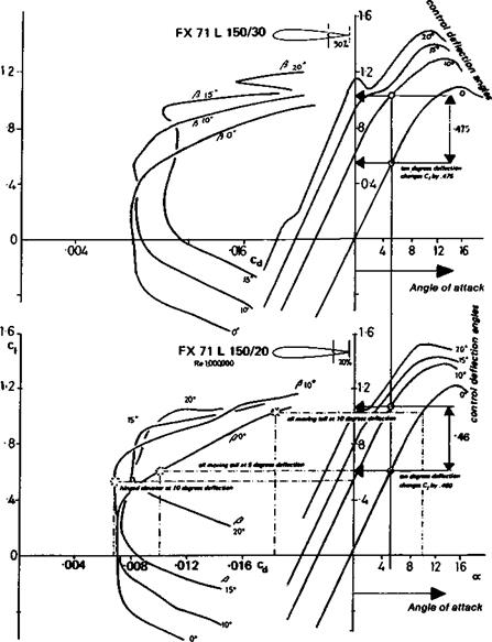
The simplest control surface is the elevator. Wind tunnel tests carried out at Stuttgart by D. Althaus on Wortmann tailplane profiles show the effect of various angular deflections of an elevator, on both the lift and drag curves, and for different sizes of hinged surface, 20% and 30% wide in terms of the chord of the whole tailplane (Fig. 13.1). The effect of a rudder on a vertical fin is of course identical. As indicated in Chapter 6, the deflection of such a surface over small angles does not change the slope of the lift curve, but moves it upwards and to the left (the elevator moving down). The c| max. increases, but the stalling angle measured geometrically decreases exactly as with a cambered aerofoil. At elevator deflections of more than 15 degrees, however, the curves show irregularities indicative of flow separation, and at the same time the drag curves show a sharp rise. As with the ordinary aerofoil section, increasing camber shifts the drag curve to higher ci positions. This is quite important since it indicates that an elevator which is trimmed to a small deflection to balance the model in flight will not necessarily generate more profile drag than when it is neutral. However, the tailplane as a whole will, in this position, probably be exerting a lifting force either upwards or downwards, and this will generate some induced drag. The wind tunnel tests also show the effect of increasing the chord of the control surface. The movement of an elevator from neutral to 10 degrees deflection with a 20% wide proportion raises Ci by approximately 0.46. Increasing the flap chord to 30% increases die effect only a very little more to about 0.47 (Fig. 13.1). The increase of control surface chord improves its effectiveness only very slightly, but the loads placed on the controlling servo motor in a model are considerably greater. The operator on the ground should be aware that any broad chord surfaces on his model are quite probably causing problems. Sometimes the control rods may bend or the model’s structure distort slightly under such loads, with the result that the actual effectiveness of the broad surface
|
|
|
is reduced. The same principles are even more valid for ailerons on both symmetrical and cambered wings: the effectiveness of the surface is increased only slighdy by broadening, but the loads on the servo are greatly magnified. If an increase of area is essential, it should if possible be achieved by increasing the spanwise extent of the hinged flap, rather than its chord. The camber of more wing surface will then be changed, with magnified effect at small cost in servo load.
The wind tunnel tests of Figure 13.1 are not, unfortunately, at low enough Re for most models. They illustrate correctly the general principles involved. They are fully valid for fast models which operate close to Re 700,000 with symmetrical or near symmetrical wing profiles. The Wortmann profiles in the 71-U-150 series (ordinates given in Appendix 3) are specifically designed for tailplanes and rudders, to give low drag when the control surface is deflected. They may be useful on aerobatic models with symmetrical wings and full-span ailerons. The aerofoils are carefully designed for use with a specific flap or elevator chord, 20,25 or 30% as indicated by the last two figures of the aerofoil designation. This should not be changed.


