Global Interpolation
An interpolation stencil may be in the form of a regular stencil in a curvilinear coordinate system, but it would be an irregular stencil when a different coordinate system is used as the frame of reference. For example, Figure 13.4 shows a regular 16-point interpolation stencil of the polar coordinate system. That is, if the r – в plane is used for computation, the interpolation stencil points form a regular stencil. But, if the computation is done in Cartesian coordinates, namely the coordinates of the stencil points are specified in a Cartesian coordinate system, the interpolation points form an irregular stencil.
In overset grids computation and in other applications, extensive interpolation from one set of mesh points of one curvilinear coordinate system to the mesh points of another coordinate system becomes necessary. Global interpolation of this type may be carried out using either coordinate system. As a test case, consider a plane wave with wave vector к inclined at 30° to the x-axis in the x – y plane. The wave function ф may be written as
|
|
where Re{ } is the real part of { }. The wave function can also be written in polar coordinates (r, в) by a straightforward coordinate transformation, thus,
ф(г, в) = Re {eikr “»<в-п/6)}. (13.40)
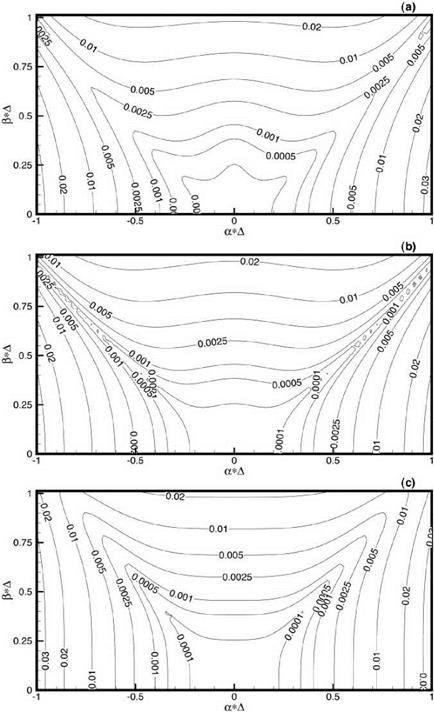
Suppose a mesh of Ax = Ay = 1 /32 in the Cartesian coordinates and Д r = 1 /32, дв = n/150 in the polar coordinate as shown in Figure 13.4 are used for interpolation purpose. Let the value of ф be known on the polar mesh points. The objective is to find ф at the mesh points of the Cartesian coordinates by interpolation using a 16-point stencil. That is, the aim is to interpolate the values of ф from the polar grid to the Cartesian grid. One obvious way is to refer the coordinates of all points to the polar coordinates system and perform the interpolation in the (r, в) plane. In the (r, в) plane the 16 interpolation points form a regular stencil. If the optimized interpolation scheme is used, it is easy to show that the matrix A (for interpolation in polar coordinate, see Eq. (13.15)) is the same for all interpolation stencils. For this reason, the inverse coefficient matrix A-1 needs to be computed only once. On the other hand, if the interpolations are carried out in the Cartesian coordinate system, the stencils are irregular. It follows that the matrix A for each point to be interpolated to is different.
One piece of information one would like to know about this global interpolation is which way of interpolation, using regular or irregular stencils, would yield the least global error. For the example under consideration, the exact wave function on the Cartesian mesh is given by Eq. (13.39). Figure 13.13a shows the interpolation error for the plane wave along the line y = 1.0 using the polar coordinates as the reference coordinates (regular stencils). Figure 13.13b shows the corresponding interpolation error when the interpolation is performed in the Cartesian coordinates (irregular stencil). It is evident from these figures that the error in Figure 13.13b is more than twice as large as that in Figure 13.13a. This strongly suggests that when global interpolation is needed, it would be best to use regular stencils. Figures 13.14a and 13.14b provide a similar comparison of global interpolation error arising from the use of regular and irregular stencils along the line x = 1.0. Again, the use of irregular stencils results in considerably larger interpolation error. Although, intuitively, the use of a regular stencil may appear to be the preferred choice, it is reassuring to see its confirmation by a concrete example.


