Plane
Whereas lines are one-dimensional, planes are two-dimensional manifolds. In Euclidean space we can safely speak about straight lines and flat planes, corroborating our experience. Our simulation may have to define such elements like ground planes, imaging planes, or target planes. Let us see how to model them in an invariant, coordinate-independent form (see Fig. 2.14).
Let the point В sweep over a whole plane, starting at Bq and maintaining R as the reference point. The movement over the plane is generated by two parameters u, є: —oo < и < +oo and v, є: —oo < v < +00 that modify the two directional vectors s ubq and s vb0 ■
Definition: A plane, subtended by sUBo and sVBr>, is defined by the sweeping
motion of the displacement vector of point В, referred to point R
sBR — US UB0 + vs VB0 + s B0R (2.23)
The plane is a two-dimensional manifold with parameters и and v.
The embedded vectors [л (/д01 and [sVHn ] stretch out the level of the plane. They do not have to be mutually orthogonal nor be unit vectors. We needed four extra points to describe the sweeping motion of B. The three points B0, U, and V establish the orientation of the plane, and R serves as reference point. If R should be in the plane, Bq could assume its function.
Example 2.6 Helicopter Landing Aid
Problem. Figure 2.15 shows a helicopter H preparing to land on an oddly shaped landing patch of a swaying ship. The pilot uses his landing aid, which displays his projection В on the landing surface, for touchdown near the center. This instrument has trackers that measure the three comers Bq, U, and V relative to the vehicle and provides them in geographic coordinates with the aid of an onboard INS. Develop the equations that are used to establish the orientation of the platform and the point В in geographic coordinates.
Solution. The platform is described by В sweeping out the plane just as Eq. (2.23) indicates
$bh = ms ub0 + vs Vb0 + s b0H
|
1G
Fig. 2.15 Helicopter landing patch. |
where sBoh is measured directly and the other two vectors are obtained from the additional measurements suh and sVh
SUB0 = SUH + S HBa; s VBu = SVH + SfJBo
where sHBo — What remains to be determined are и and v. We can calculate
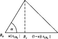
them with the help of the scalar product and trigonometry. Let us do it for u, and, by analogy, the solution for v follows. Referring to Fig. 2.16 and Eq. (2.15), we derive
ShB0SuB0 u pt/fio
cos a = і——- r-j—– г = – p—— p
SHB0 pr/flol sHBo
and solving for и
_ SflBpS un„
SUB0
|
H
|
Similarly,
![Plane Подпись: [^c/fio]0 = ISUH]G + [sr/Bo] ; [WBO] — [WH]0 + [jvffio] [■Sfitf]0 = u [ri/fi,, ] + + K«]](/img/3132/image041_1.gif) |
The problem was solved entirely in symbolic form. The processor of the instrument carries the calculations out in the same geographic coordinates that the measurements [іВон]с, lri///lG, and [sVH]G are given:
and the projection of the helicopter on the landing platform is calculated from or in the platform plane
[■Sfifio]0 — U’fitfl6 ~ [/fir,//]
Review briefly our two-step approach. We first derived the solution in vector form without reference to coordinate systems or their origins, followed by the coordinate form for programming. You can practice computing a sample numerical solution by solving Problem 2.2.


