Line guidance, scalar case
In some applications it is desirable that the target point is approached from a certain direction. For instance, an aircraft coming in for a landing must, while descending along the glide slope, line up with the the runway and approach an initial point (IP) at the beginning of the runway before touchdown. The IP is the target point, and the heading and depression angles define the approach line. A second example describes the delivery of submunitions against tanks traveling on a highway. The cruise missile, which carries the submunitions, must approach in the direction of the highway and start dispensing the submunitions at the head of the tank column. Again, an approach line and IP must be defined. Other applications include the delivery of hard target warheads along a steep trajectory, reconnaissance flights along railroad tracks, and waypoint guidance with desired headings.
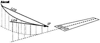
The task of line guidance is to align the vehicle toward the line and keep the velocity vector aligned until the vehicle flies through the IP. We call this line the line of attack (LOA) in contrast to the LOS, which is the line between the vehicle c. m. and the IP. Figure 9.24 depicts the geometry for the landing approach of an aircraft.
The objective of line guidance is to drive the LOS toward the LOA. As they merge, the aircraft will fly through the IP along the desired approach line. Let us first derive the governing law for horizontal steering, which can be visualized as the horizontal projection of Fig. 9.24.
 |
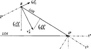
In addition to the LOS coordinate system ]°, we define the coordinate system F associated with the LOA of the final approach (see Fig. 9.25). The velocity of the aircraft В wrt the Earth frame E is vf, and its two components in the 2 direction of the ]7′ and ]° coordinates are (uf )£ and (v^)®■ To accomplish the objective of line guidance, both components must be driven to zero by the acceleration command, normal to the velocity vector. From these considerations we formulate
|
the horizontal line guidance law
![]() {a)v2=K[-{vEB)°+G(vEB)F2}
{a)v2=K[-{vEB)°+G(vEB)F2}
The velocity vector is turned towards the IP if the acceleration command {a) reduces the (uf )0 component. The aircraft c. m. В is moved faster toward the LOA if (a)2 increases the (vB)[ component. The G gain balances the two terms, and the К gain adjusts for the different units. When vf is on the LOA, both components are zero. Gain К is the guidance gain and is usually selected to be constant with values between one and three. The bias gain G, on the other hand, needs to decrease as the aircraft approaches the IP point, or else, dynamic overshoot can prevent the aircraft from flying through the IP. I found an exponential decrease suitable for all applications
![]() (9.60)
(9.60)
where |5гв| is the distance of the vehicle to the IP and d is the norm distance at which the gain has the value G = 0.633. A typical value is d = 1000 m.
The development of the line guidance law for the vertical plane is similar. Applying Eq. (9.59) to the third directions of the coordinate systems ]v, ]°, and ]F yields
![]() (а)з = K[-(vEB)° +G(uf)[] g cos YL
(а)з = K[-(vEB)° +G(uf)[] g cos YL
with the gravity bias term g cos Yi. Note that (a)^ is positive down and normal to the velocity vector v f. For small angles of attack the normal load factor command is approximately aNc = — (a)^; otherwise, we use амс = — (a)^ cos a. In the horizontal plane the lateral acceleration command is aic = (a)^ ■
Most line guidance applications have a fixed IP point (or target) from which emanates a fixed LOA. As an extension, only slow target movements compared to the missile speed can be accommodated. If G = 0, we have the special case of
point guidance, also called pursuit guidance, with the velocity vector of the vehicle pointed at the target, irrespective of the approach direction.


