Category Aircraft Flight

The economics of high speed

In the discussion above and in Chapter 6 we discovered that the jet engine’s performance in terms of efficiency improves with speed, eventually becoming higher than that of the piston engine/propeller combination. As we increase the cruising speed, or Mach number, so we can employ power plants having a steadily improving efficiency.

An idea of the overall efficiency of the airframe/engine combination can be obtained by multiplying the airframe efficiency (best lift/drag ratio) by the engine efficiency. The result of this is shown in Fig. 7.9 and indicates that this overall efficiency can be kept surprisingly constant with speed. Thus for a given journey we can in principle construct an aircraft which will cruise at high speed and only use the same amount of fuel as its low speed competitor.

The above argument does not imply that the overall efficiency of an indi­vidual aircraft does not vary with speed. It merely means that we can design particular configurations intended for operation at widely differing speeds, with similar overall efficiencies.

The economical operation of a commercial aircraft is not just a matter of the amount of fuel used per passenger on a given flight. Aircraft cost a great deal and must complete as many flights per day as possible to pay their way. Crews have to be paid by the hour; and the airline which can provide the fastest service will generally attract the most passengers – other factors being equal. These factors clearly make the high speed aircraft a very attractive option.

Again we must beware of making too sweeping conclusions from such an argument. The design of a particular aircraft to fill a particular slot in the market is very complicated. Development costs, especially for supersonic and

THE ECONOMICS OF HIGH SPEED 203

Fig. 7.9 Overall aircraft efficiency

This figure represents best achievable figures. As airframe efficiency declines achievable propulsive efficiency rises to compensate

hypersonic configurations where little previous experience is available, are very high. We also have to remember that we have only considered the problem assuming we can cruise our aircraft at its optimum speed throughout the flight. The Concorde, which is an example of a supersonic transport, had to spend a substantial part of the flight cruising at subsonic speed to avoid creating too much disturbance on the ground with its shock waves. It may also have to spend some time queueing to land. These factors may significantly increase the fuel usage over the flight and a comparatively small change in fuel prices may nullify the other commercial advantages described above. In spite of these difficulties Concorde showed a good operating profit.

We also find certain ‘natural breaks’ in the scale of economical cruising speeds. At a flight Mach number in the region of unity we know that there is a rapid increase in the drag which can be achieved for a given lift. It is some time before the improved engine efficiency makes up for this. It is for this reason that there is a gap in the cruising speed of transport aircraft between the majority of aircraft which cruise at flight Mach numbers of approximately 0.8 and Concorde which cruises at a Mach number of 2.

Concorde represents another limit, that imposed by kinetic heating. Above this Mach number serious problems begin to be encountered with conventional light alloy materials and greatly increased development and construction costs must be accepted.

However, the more general argument for high speed, aimed at very long-term developments, is of interest in sorting out the practical from the pipedream. As Dietrich Kuchemann (1978), an aerodynamicist who has contributed much to the development of high speed aircraft, points out, the semi-orbital hypersonic airliner travelling to Australia from the UK in a couple of hours may well be a sensible long-term goal.

Dealing with the wing centre section

We mentioned above that the wing centre section posed problems as well as the tip region. Although in the real aircraft there will, in general, be a fuselage, we can get a useful insight into the basic problem by first considering the wing in isolation.

The problem is, in some ways, very similar to the tip problem that we have already discussed. We see a similar reduction in sweep of the isobars to that encountered at the tip (Fig. 9.16(a)). However because of the mutual influence of the wing sections further outboard and the influence of the trailing vortex system, the loading at the centre section becomes less, rather than more peaky (Fig. 9.14), and, in addition, the overall loading in the centre section becomes lower because of this effect.

Neither of these effects is particularly welcome. If the centre section loading is less ‘peaky’ there will be an even greater tendency for stalling to take place first at the tip region, which, as we have already seen is undesirable. The loss of overall load in the centre region is also undesirable because this means that the wing will have a reduced overall efficiency. There is also a structural implica­tion because the bending moment on the wing will be increased if the load is concentrated towards the tips.

The same methods can be used to solve the problems at the centre section as were used for the tips – we can alter the aerofoil thickness, or its camber or we can twist the wing to alter the local angle of attack. We can also change the planform in this region, but this again is frought with structural and other problems which we will examine later.

By introducing local changes in the section we aim to make the load distri­bution approach, as far as possible, the distribution which is obtained on the infinite sheared wing. In order to maintain the sweep of the lines of constant pressure (isobars) at the centre section, the point of maximum thickness can be moved forwards on the section. At the same time a local negative camber is used which again shifts the centre of loading towards the front of the section. By these means we can, at the design condition, achieve a reasonably efficient load distribution while, at the same time, encouraging stall to occur at the inner section before the tip region.

Static stability

Solving the problems

The precise analysis of aircraft stability is an extremely complicated process. For conventional straight-winged aircraft in the pre-jet age, it was found that by making a few simplifying assumptions, the problems could be reduced to a form where they could be solved by traditional analysis and hand calculations. Some aspects of this approach are still perpetuated in introductory texts and courses, because the simplification can act as an aid to understanding. The increasing aerodynamic complexity of aircraft has, however, rendered many of the assumptions inappropriate, and for industrial purposes, a more complete solution of the stability equations is normally attempted. This direct approach has been made practical by the advent of the digital computer, but despite the advances that have been made in theoretical methods, the analysis of air­craft stability still represents a considerable challenge, particularly for uncon­ventional types such as the forward-swept X-29 shown in Fig. 9.20.

Although we shall not attempt to describe the process of stability analysis, we can at least explain some of the principles and design features involved in producing a stable and controllable aircraft.

The requirements for trim and stability

For steady flight, the forces acting on an aircraft must be in balance, and there must be no resultant turning moment about any axis. When this condition is achieved, the aircraft is said to be trimmed. In Fig. 11.1 we show an aircraft that is trimmed about its pitching axis.

An aircraft is said to be statically stable if it tends to return to its initial flight conditions; attitude, speed etc., after being disturbed by a gust or a small

Weight

For aircraft to be trimmed L„x a – M0 = L, x b

Fig. 11.1 Forces on an aircraft trimmed for steady level flight

The movements about the centre of gravity due to wing lift, the tail downforce and the pitching couple are exactly in balance

In this simple example we have chosen a case where the thrust and drag forces are on the same line. This is not generally true, and thrust and drag forces normally affect the trim. Fuselage effects have also been ignored impulsive input from the controls. Normally, for steady flight, we require the aircraft to be both trimmed and stable.

There is frequently considerable confusion about the difference between balanced or trimmed, and stable. If you balance a ball on the end of your finger, it may temporarily be perfectly balanced, but it is certainly not in a stable position.

In general, the more stable we make an aircraft, the less manoeuvrable it becomes. A very stable aircraft always tends to continue on its existing path, so excessive stability must be avoided.

We can quickly get some idea of how stable an aircraft is by ignoring inertia or time-dependent effects, and just looking at the balance of the forces and moments acting on the aircraft; in other words, by treating the problem as if it were one of statics. Once it is established that an aircraft is statically stable it is then necessary to go on to investigate the inertia and time-dependent effects; the so-called dynamic stability described in the next chapter. This approach was part of the traditional method of breaking down the complex problem of aircraft stability, and although computational techniques have to some extent rendered it unnecessary, it is still useful, particularly when introducing the subject.

Approach and landing

The landing is the most difficult task the pilot has to undertake. It requires an accurate approach to position the aircraft correctly in relation to the runway, together with precise control during touch-down which may be complicated by winds blowing across the flightpath.

Figure 13.6 shows the stages from initial approach to touch-down. Some way out from the runway the aircraft speed is reduced and high lift devices extended to reduce the minimum flying speed. A typical landing configuration is shown in Fig. 13.7. Comparing this with the corresponding take-off con­figuration it can be seen that a lot more trailing-edge flap is used because extra drag is, of course, a positive advantage during landing, both from the point of view of the final deceleration of the aircraft and because a high drag configura­tion leads to easier speed control.

At the start of the landing manoeuvre the aircraft is aligned with the runway and put into a steady descent along the ‘glide path’. As the runway threshold is reached the angle of attack is increased so that the rate of descent is reduced and the aircraft is ‘flared’ so that it flies just above and nearly parallel to the runway until the touchdown point is reached. At this point the aim is to stop as quickly and safely as possible. In order to provide aerodynamic braking and

Fig. 13.7 Landing configuration

The BAe 146 with everything deployed. Double flaps fully extended. Lift dumpers deployed above the wings to increase drag and destroy lift, and rear airbrake doors wide open

to sit the aircraft firmly on the runway ‘lift dumpers’, or spoilers, may be used Fig. 13.7. Jet aircraft frequently use thrust reversers (Fig. 6.32) to provide further deceleration and to relieve the wheel brake requirement. Some military aircraft even resort to the use of a braking parachute to shorten the landing run.

Spoiled for choice

Until the mid-1940s, the only method of lift generation was by means of attached flow on a fixed, or occasionally, a rotating wing. From the descrip­tions above, you will see that nowadays, several different methods are used. In addition, as we show later, even with a conventional wing, the physical mech­anism of lift generation changes at high speeds and at very high altitudes.

We will deal with the details and implications of these newer methods in subsequent chapters. In the next chapter we show how the generation of lift by a wing also involves strong three-dimensional features.

Recommended further reading

Abbott, I. A., and von Doenhoff, A. E., Theory of wing sections, Dover Publications, New York, 1949.

Fay, John, The helicopter: history, piloting and how it flies, 4th edn, David and Charles, Newton Abbot, UK, 1987, ISBN 0715389408. An updated edition of a popular book that gives a good general introduction to the subject of helicopters.

Seddon, J., and Newman, S., Basic helicopter aerodynamics, 2nd edn, Blackwell, London, 2002, ISBN 9780632052837.

The pros and cons of high lift devices

The high lift coefficients obtained with both leading and trailing-edge devices incur a penalty in terms of drag, but this may be acceptable or even useful in landing, as described in Chapter 13. Note the extreme amount of curvature used on the flaps of the Andover shown in Fig. 3.16.

For take-off, it is normal to use a configuration giving lower CL and less drag. Smaller flap angles are almost invariably used.

There are many versions of slot, slat and flap, in addition to the examples illustrated in Figure 3.13. Their effectiveness depends on the precise geo­metry of the device, and on the type of aerofoil section used. It is therefore impractical to try to indicate a figure for the order of improvement in CL for competing designs. Generally, and unfortunately, the most effective devices tend to be the most complicated and heaviest.

Transonic drag rise and centre of pressure shift

The dramatic change in flow from subsonic to supersonic conditions is, as might be expected, accompanied by marked loading changes on the aerofoil. One important consequence of this is a rearward shift in the centre of lift.

The formation of the shock waves as the flow develops in the transonic speed range leads to the formation of a large separated wake (Fig. 5.18(b)). This in turn leads to a very rapid drag rise over a small Mach number range.

Transonic drag rise and centre of pressure shift

Подпись: TRANSONIC DRAG RISE AND CENTRE OF PRESSURE SHIFT

This shock wave is a reflection from the tunnel wall


(b)


(c)


Fig. 5.18 Shock wave development on a conventional aerofoil

(a) Subsonic flow with no shocks (b) Transonic flow. The approaching flow is subsonic, but patches of supersonic flow develop downstream of the leading edge, terminating in a shock wave on both upper and lower surfaces (c) Supersonic approach flow. Oblique shock waves initiated at the leading edge slow the flow to a lower Mach number than the approach. The flow then accelerates to a higher Mach number, and is finally reduced again via a second pair of shock waves at the trailing edge


Transonic drag rise and centre of pressure shiftTransonic drag rise and centre of pressure shift

Transonic drag rise and centre of pressure shift

Fig. 5.19 Effect of Mach number on lift and drag coefficients at constant angle of attack

Shock induced separation causes a rapid increase in drag coefficient in transonic region

The drag rises much more rapidly than the dynamic pressure so that the drag coefficient rises. The drag coefficient falls again as the fully supersonic flow pattern is established and Fig. 5.19 shows the typical transonic drag coefficient peak which is of great importance in the design of both transonic and super­sonic aircraft as we shall see in later chapters.

Figure 5.19 also shows that the lift coefficient varies significantly as the speed of sound is approached. It should be noted that Fig. 5.19 shows the vari­ation of lift and drag coefficients at constant angle of attack. If the angle of attack is varied as the flight speed is changed in order to keep the overall lift (rather than the lift coefficient) constant, as would be the case in cruising flight, then a slight fall in the drag coefficients is frequently experienced just prior to the rapid rise as the speed of sound is approached. This occurs because the increase in lift coefficient means that the angle of attack can be reduced. This local reduction in drag coefficient can be usefully exploited in design.

Ultra-high by-pass (UHB) engines, prop-fans and unducted fans

In the quest for improved efficiency, engines with much larger by-pass ratios than the early turbo-fans have been designed. Both ducted and unducted designs have been devised, and examples are illustrated schematically in Fig. 6.27. In some of the designs a gearbox is incorporated in order to reduce rotational, and hence, blade tip speed. Contra-rotating fans are normally used.

There is no standard classification of such engines, and the term ‘prop-fan’ is used loosely to describe various different types. There is also something of a grey area in terms of whether a design should be classified as an unducted fan, or simply an advanced propeller.

The major problem with very high by-pass ratio engines, is the noise that their supersonic blade tips produce. Rear mounting of the engines can reduce the cabin noise and noise-induced structural fatigue. It also eliminates the pos­sibility of the pressurised fuselage being punctured in the event of a blade shear­ing off. Unfortunately, from practical considerations, rear mounting limits the number of engines to two, or possibly three.

For really large transatlantic aircraft, four engines are normally preferred, and in this case, wing mounting must be used. The ducted design shown in Figs 6.27(c) and 6.28 is intended for use on such aircraft, cruising at high sub­sonic Mach numbers. The reduced intake Mach number that can be obtained

Ultra-high by-pass (UHB) engines, prop-fans and unducted fans

Fig. 6.28 The Rolls-Royce contra-rotating very high by-pass fan concept. No gearbox is used, and the fan blades are connected directly to contra-rotating turbines

Ultra-high by-pass (UHB) engines, prop-fans and unducted fans

Fig. 6.29 Unducted fan propulsion

The Macdonnell-Douglas MD-80 unducted fan demonstrator aircraft fitted with the gearless General Electric UDF® engine; front-runner in the race to develop this type of powerplant. Dispensing with the gearbox considerably reduces the weight and mechanical complexity of the engine (Photo courtesy of General Electric Co.)

with a duct is an advantage for flight at such Mach numbers, as explained earlier. The duct also affords some noise shielding and containment in the event of shedding a blade.

For twin-engined transports and for cruise Mach numbers up to 0.86, the even higher-efficiency unducted designs are preferable. Figure 6.29 shows the General Electric gearless unducted fan (UDF®) installed in the MD-80/UDF demonstrator, where it has shown exceptionally low fuel consumption and low community noise, as well as a cabin environment equal to or better than today’s turbo-fans. Its commercial success still needs to be demonstrated.

Ultra-high by-pass (UHB) engines, prop-fans and unducted fans Ultra-high by-pass (UHB) engines, prop-fans and unducted fans
Ultra-high by-pass (UHB) engines, prop-fans and unducted fans

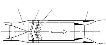
Ultra-high by-pass (UHB) engines, prop-fans and unducted fansFig. 6.30 A reheat chamber or afterburner

The exhaust from a gas turbine still contains a large proportion of oxygen which can be used for burning additional fuel in the reheat chamber. This can produce a considerable amount of extra thrust

Reheat is often used for take-off on combat aircraft with high wing loadings. It is also used at high supersonic speeds, and for rapid acceleration and climb

Planforms for supersonic flight

So far we have only looked at the effect of the aerofoil cross-sectional shape on the aerodynamic performance of the lifting surface. We know that in subsonic flight the planform shape has a vital role to play, and the same is true above the speed of sound.

The unswept wing

Let us first take a look at the unswept wing. We have already seen what the flow is like when we consider a two-dimensional section and ignore any

3-dimensional flow at wing tip

Intersection of wing surface and tip Mach cone

Wing trailing edge

Shock wave

Mach cone

Curved shock wave

Fig. 8.7 Wing-tip effect in supersonic flow (unswept wing)

influence from the tips. Let us now consider the more realistic situation in which the wing has a finite span so that the tips will have an influence on the wing behaviour.

When we considered subsonic wings (Chapter 2) we saw how the tip affected the flow everywhere. In a supersonic flow we found (Chapter 5) that because of the way pressure disturbances are propagated, only a limited region of the flow can be affected by the presence of an object. Thus we find that the influence of the tips is restricted to a limited region and the centre section of the wing behaves in a purely ‘two-dimensional’ way as though the tips were not there at all.

The region over which pressure disturbances from the tip can propagate will be bounded by the ‘Mach cone’ (Fig. 8.7). The Mach lines making up the surface of this cone are determined by the local flow conditions at each point along their length. Thus, in general, the local slope of the Mach line, and consequently that of the surface of the Mach cone, will vary and the surface will be warped slightly. Further the geometry of the cone will also depend on the wing incidence. In the centre region, outside the tip Mach cones, the flow knows nothing about the existence of the tip region and the flow is the straightforward two-dimensional flow discussed earlier.

Further from the surface the tip Mach cone intersects the oblique bow shock wave generated by the wing centre section (Fig. 8.7). The shock is therefore

Fig. 8.8 Unswept wing for supersonic flight

In supersonic flight the unswept wing of the F-104 is relatively efficient, but in subsonic flight, the highly loaded razor-thin wing gives poor handling, and a high stall speed. Like the Lightning, it was designed as a high performance interceptor at a time when almost total reliance was placed on air-to-air missiles. Manoeuvrability and dog-fight capability were considered of little importance (Photo by N. Cogger)

altered in the tip region and the outer region of the tip flow becomes bounded by a conical shock wave as shown in the figure.

Because the tip can influence the flow within its Mach cone, the flow in this region develops a spanwise component which is absent in the two-dimensional centre region of the wing. This spanwise velocity results in a circulation around the tip from the high-pressure lower surface to the low-pressure upper surface. Trailing vortices are thus formed in a manner similar to a subsonic wing.

If the wing is unswept a sharp leading edge is required to reduce the wave drag and, since such wing sections have poor low speed performance, they are not employed when this aspect is important. Figure 8.8 shows the F-104, one aircraft where such a planform was employed for high speed.

Swept wings

In Chapter 2 we saw how wing sweep could be used to reduce the component of velocity approaching at right angles to the wing leading edge. If the wing is

swept back sufficiently to make this velocity component less than the velocity of sound then the wing will behave as though in a subsonic air stream.

In order to simplify the discussion we will return to the consideration of a wing of infinite span. In this way we can initially ignore both the problem of the wing tip and that of the ‘cranked’ centre section of the wing.

Slab, all-moving and all-flying tail surfaces

For subsonic aircraft, it is normal to have a fixed tail surface and movable ele­vators as seen in Fig. 10.5. Supersonic aircraft, however, are usually fitted with an all-moving or slab tail surface, where pitch control is obtained by changing the incidence (inclination relative to the fuselage) of the whole horizontal tail surface. A slab tailplane may be seen on the F-18 in Fig. 10.6. This arrangement is advantageous for high speed aircraft, because in supersonic flow, changes in camber do not significantly affect the lift. Deflection of a conventional hinged elevator does produce a change in lift, but this is mainly because it effectively alters the angle of attack, as shown in Fig. 10.7. As we described in Chapter 5, a supersonic flow can readily negotiate the sharp change in direction produced by the inclination of a slab surface, and the plane slab surface produces less drag in supersonic flow than a cambered one.

The slab tailplane has also become popular on light aircraft. This is partly because greater control forces can be produced by moving the whole surface,

Fig. 10.6 An F-18, with slab tail, twin fins, and full-span control surfaces on the wing

The engine exhaust nozzle in the minimum-area convergent configuration for subsonic flight

Fig. 10.7 In supersonic flow, deflection of a conventional camber-change elevator produces an increase in lift mainly because the angle of attack is effectively changed. The camber-change produces little effect. The plane slab surface produces less drag. In supersonic flow the air can negotiate the sudden change in direction (a) Camber-change control surface (b) Incidence-change slab control surface

and partly because it enables the tailplane to be moved out of a stalled condi­tion, if this should inadvertently happen in a violent manoeuvre.

Another variant is a tailplane which is provided both with elevators, and a means of changing the tail incidence. This feature is commonly used on large T-tailed aircraft. The variable incidence action is usually employed to trim or balance the aircraft for steady flight, with the elevator being used for control in manoeuvres. This mode of operation requires a separate control for the incidence-change mechanism and elevators. An alternative arrangement is to link the incidence and elevator mechanisms. The use of combined camber and incidence control, enables the surface to produce greater force than could be provided using either control separately. The maximum force that can be produced by a control surface is often limited by the onset of stalling of the surface. The improvement in control obtainable with such ‘all-flying’ tails has to be balanced against the increased complexity and weight.