Category Fundamentals of Modern Unsteady Aerodynamics

Momentum, Equation

The Newton’s second law of motion, based on the conservation of momentum, is applicable only on the systems. According to this law, the forces acting on the system cause a change in their momentum. For a system which is not under the influence of any non-inertial force, let FS be the surface force acting at time t. This surface force changes the N = MV momentum of the system. Here, if we let the momentum be independent of mass, then we find for the relevant property g = N/ M = V. We can now write the balance between the surface forces and the cor­responding moment changes at the system which coincides with the control vol­ume at time t.

Vs = O-JJJPV dV+j^PV(V • dA) (2.36)

The forces at the surface of the system can be considered as the integral effect of the stress tensor s over the entire surface of the control volume: FS = fflx. dVA. If we use this on the left hand side of Eq. 2.36 and change the surface integrals to volume integrals with the aid of divergence theorem we obtain

JJJV.(l)dV = 0.JJJp~dJ+JJJV •(p VV)d8 (2.37)

Here, the double arrow and the velocity vector multiplied by itself indicate the tensor quantities. Equation 2.37 can also be expressed in differential form to give the local expression of the momentum equation as

0pV + V • (pV V — ?) = 0 (2.38)

In Eq. 2.38, the stress tensor includes in itself the pressure, velocity gradient and for the turbulent flows the Reynolds stresses and reads like

s = (—p + kV • V)I + іsim ~— <pvv > (2.39)

Here, I is the unit tensor and simV is the symmetric part of the gradient of the velocity vector. According to Stoke’s hypothesis, the coefficient k = -2/3 і, wherein the average viscosity of the species is denoted by p. Equation 2.38 is valid only for the inertial reference frame. If we include the inertial forces, we consider a
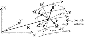
control volume in a local non-inertial coordinate system xyz accelerating in a fixed reference frame XYZ. Let the non-inertial coordinate system xyz move with a linear acceleration R" and rotate with angular speed X and the angular acceler­ation X’ in the fixed coordinate system XYZ as shown in Fig. 2.5.

Let the control volume in Fig. 2.5 be attached to the non-inertial frame of refer­ence xyz. The infinitesimal mass element pdV considered in the control volume in the fixed reference frame XYZ has the acceleration aXYZ. At this stage, the relation between the acceleration a^ in the non-inertial frame and the acceleration aXYZ in the inertial frame in terms of linear acceleration: R", Coriolis force: 2’XxVxyz, centripetal force: Xx(Xxr) and X’xr reads as given in (Shames 1969)

aXYZ = axyz + R’ + 2XxVxyz + Xx(Xxr) + X’xr (2.40)

Here, Vxyz is the velocity vector in xyz and r is the position of the infinitesimal mass pdV in xyz coordinate system. If we write the Newton’s second law of motion in the fixed reference frame for the infinitesimal mass at time t using Eq. 2.40 we obtain

dF = p dV aXYZ = p dV [ axyz + R” + 2XxVxyz + Xx(Xxr) + X’xr] (2.41)

Equation 2.41 can be written for the acceleration in the non-inertial reference frame in terms of the inertial forces

p dV axyz = dF — p dV [R” + 2XxVxyz + Xx(Xxr)+ X’xr] (2.41a)

We know that F = JdF. As the new form of the momentum equation expressed in the non-inertial reference frame xyz we obtain ~S

Подпись:p dV = o P~ dV+ ^ pV (V • dA)

(2.42)

Momentum, Equation image27

If we consider the surface forces expressed in terms of stress tensor the dif­ferential form of the momentum equation becomes

Equation 2.43, can be used, in general, for studying the pitching and heaving – plunging airfoils and finite wings in roll and viscous analysis for drag prediction of fuselages.

Global Continuity and the Continuity of the Species

Continuity equation: If M is the total mass in the system then N = M and for the system DN/Dt = DM/Dt = 0. In addition, since g = M/N = 1 Eq. 2.27 reads

(2.28)

Using the divergence theorem, the second term at the right hand side of Eq. 2.28 reads as (Hildebrand 1976),

JJJV.(qU)dV = фp (~ . dA) (2.29)

The new form of Eq. 2.28 becomes

JJJJp dV + JJJ V. (qA)dV = JJJ (jjp + V. (pU)^dV = 0 (2.30)

In Eq. 2.30, the control volume does not change with time therefore, the time derivative can be taken into inside of the first term without causing any alteration. Since the volume element dV is arbitrary and different from 0, to satisfy Eq. 2.30 the integrand must be zero to give the differential form, strong form, of the continuity equation.

OP + V.(p~) = 0 (2.31)

At high temperatures when the real gas effects take place, the air starts to disassociate and chemical reactions create new species. Because of this, we may need to write continuity of the species for each specie separately. If we consider specie i whose density is pt and its production rate is W in a control volume, then we have to have a source term at the left hand side of Eq. 2.27.

Iff WdV = OiIff Р^+ ff Pi (Ai-dA) (2.32)

Here, the velocity V, is the mass velocity of specie i. The differential form of Eq. 2.32 reads as

JPi +V. (Pi-Ui) = Wi (2.33)

Defining the mass fraction or the concentration of a specie with c, = p/p, the total density then becomes p = Rc;p;. The mass velocity Vi of a specie in a mixture is related with the global velocity as follows: V = Rc;V,. A mass velocity of a specie is found with adding its diffusion velocity Ui to the global velocity V i. e., Vi = V + Uj. According to the Ficks law of diffusion, the diffusion speed of a specie is proportional with its concentration. If we denote the proportionality constant with Dmi the diffusion velocity of i reads

Подпись: (2.34)U i ciDmiV ci

If we combine Eq. 2.34 with 2.31 and use it in Eq. 2.31, we obtain the conti­nuity of the species in terms of their concentrations as follows (Anderson 1989),

Подпись: (2.35)Dci ~ . .

q— = v • p (DmiVc^ + Wi

System and Control Volume Approaches

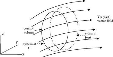
Let V(x, y, z, t) be the velocity vector field given in a stationary space coordinate system x, y, z and time coordinate t. Shown in Fig. 2.4 is the closed system composed of air coalescing with a control volume at time t. The control volume remains the same at time t + At the system, however, as the collection of same particles, moves and deforms with the flow as shown in Fig. 2.4.

Let N be the total thermodynamical property in our system. Because of the flow field, there will be a change with time in the property N as DN/Dt. Let g be the specific and local value of property N, which is distributed throughout the control volume. The total value of this property can be represented as an integral as follows: N = Jgp dV. Here, dV shows the infinitesimal volume element in the control volume. Now, we can relate the time rate of change of property g in the control volume in terms of its flux through the control surface as the control volume coincides with the system as At approaches zero. Under this condition, the flux of g from the control surface will be fflgp(V ■ dA), (Fox and McDonald 1992). If we consider the limiting case as the system coinciding with the control volume, the total derivative of the property N in the system can be related to the control volume as follows

DNN=I# gp# gp(VdV) (2.27)

where V = ~. Now, we can apply the conservation laws of mechanics to Eq. 2.27 and obtain the strong forms of the governing equations.

Real Gas Flow

The real gas flow equations are free of all the restrictions given above. Therefore, they are first introduced in their weak form, integral form, in terms of the system and control volume approaches.

image26

Fig. 2.4 The velocity vector field V(x, y, z, t), the system and the control volume

Moving Coordinate System

The linearized equations which are obtained previously enable us to analyze aerodynamical problems more conveniently. Let us now elaborate on the coor­dinate systems which will further simplify the equations. The type of external flows we study usually considers a constant free stream velocity U at the far field. The reference frame used for this type analysis is a body fixed coordinate system which moves in the negative x direction with velocity U. Another type of analysis is based on the moving reference system which moves with the free stream. With this type analysis, the form of the equations looks simpler to handle. Let us write Eq. 2.24b in the moving coordinate system which moves with the free stream. Let x, y, z be the body fixed coordinate system and, x0, y’, z’ be the flow fixed coor­dinate system. As seen from Fig. 2.3, since the free stream velocity is U, after the time interval t the flow fixed coordinate system translates in x direction by an amount Ut.

The relation between the two coordinate system reads as x = x — Ut, y = y, z = z, t = t.

The derivative with respect to t0 becomes

0 0 0 0x 0 0

0t’ 0t ^ 0x’ 0t 0t ^ 0x’ U.

Here, %= -U.

image25"Fig. 2.3 Body fixed x, y, z and the flow fixed x’, y’, z’ coordinate systems

The partial derivatives with respect to body fixed coordinates in terms of the flow fixed coordinates then become:

0 _o__o _0-A _0-A _0-A

Подпись: V2/' Подпись: _1 0V a10t'2 Подпись: 0

0t ^ 0x 0t’ 0x 0x’ 0y 0y’ 0z dz’ Equation 2.24b in the flow fixed coordinate system reads as

The last equation is in the form of the classical wave equation whose solutions are well known in mathematical physics. The boundary conditions and the pres­sure coefficient expressions, Eqs. 2.20 and 2.21, become:

Подпись: 0Za 0t' Подпись:Boundary condition: w

Pressure coefficient: Cp

2.1.5.1 Summary

Hitherto, we have given the linearized form of the potential equations which are applicable to various problems of classical aerodynamics. In order for these equations to be valid in our modeling, the following assumptions must be true:

1. The air is considered as a perfect gas.

2. Mass, momentum and the energy conservations are used.

3. Body forces, viscous forces and the chemical reactions are ignored.

4. The flowfield is assumed to be either incompressible or barotropic.

5. The slopes of the body surfaces and all the flowfield perturbations are assumed to be small.

6. The time rate of change of the flow parameters are assumed to be small.

In addition, the linearized form of the compressible flow is only valid for subsonic and supersonic flows. The nonlinear approaches for the transonic and the hypersonic flows will be seen separately in relevant chapters.

Acceleration Potential

Another useful potential function which is used in aerodynamics is the acceleration potential. If we recall the momentum equation for barotropic flows:

Dq

Dt

As seen in the left hand side of the equation, the material derivative of the velocity vector is obtained from the gradient of a function of pressure and density only. Hence, we can define the acceleration potential as follows

Подпись: vw.Dq

Dt

As a result of last line the momentum equation reads as,

vw + v Z — = 0 J p

The integral form of the last equation becomes

W = -/ ^ + F(t)

p

The pressure term integrated at the right hand side of the equation from free stream to the point under consideration gives,

w = Pi—p p

Подпись: V Подпись: 0/ 0t Подпись: 2 Подпись: dp P. Подпись: 0.

Because of the direct relation between the pressure and the acceleration potential, this potential is also called the pressure integral. Let us rewrite the Kelvin’s equation in gradient form

Подпись: V Подпись: +і - w 0t 2 W Подпись: 0.

We can now find the relation between the velocity potential and the accelera­tion potential as follows

The integral of the last equation

00/+qr – w=F(t)

Once again if we choose F(t) = U2/2 we can satisfy the flow conditions at infinity. Hence, the acceleration potential becomes,

, 0/ q2 U2

w = а7 + Т – IT

With small perturbation approach, the linear form of the last line reads

image23

If the linear operator

Acceleration Potential Подпись: 0;
image24

operates on Eq. 2.24b to give

Interchanging the operators and utilizing Eq. 2.25 gives us the final form of the equation for the acceleration potential

Подпись: v2w(2.26)

Linearization

Let us begin the linearization process with the boundary conditions. The small perturbations approach will be used here. Accordingly, let U be the free stream speed in positive x direction, Fig. 2.1.

Подпись: 0ф' Ox Подпись: ' o/' “; 0y Подпись: v Подпись: and Подпись: 0ф' 0z Подпись: w.

Let “ be the perturbation velocity component in x direction which makes the total velocity component in x direction: “ = U + “’.In addition, defining function ф’ as the perturbation potential gives us the relation between the two potentials as follows: ф = ф’ + Ux. As a result, we can write the relation between the pertur­bation potential and the velocity components in following form

Подпись: Fig. 2.1 Coordinate system and the free stream U Подпись: U Подпись: y

The small perturbation method is based on the assumption that the perturbation speeds are quite small compared to the free stream speed, i. e. “’, v, w ^ U. In addition, because of thin wing theory the slopes of the body surface are small therefore we can write

Linearization
Подпись: t0 za 0 za
Подпись: T0za 0x

which gives the approximate expression for the boundary condition

w = 0za + U0za (2.20)

0t 0x v ;

Equation 2.20 is valid at angles of attack less than 12° for thin airfoils whose thickness ratio is less than 12%. For the upper and lower surfaces, the linearized downwash expression will be denoted as follows.

Upper surface (u) : w = + U0"; z = 0+

0t 0x

Lower surface (l) : w = + U; z = 0-.

ot ox

Now, let us obtain an expression for the linearized surface pressure coefficient. For this purpose we are going to utilize the linearized version of Eq. 2.8. The second term of the equation is linearized as follows

q2 U2 .

ffi + 2U"

22

For the right hand side of Eq. 2.8 if we arbitrarily choose F(t) = U2/2 then the term with the integral reads as

dP 0/ ,

2U " .

P 0t

The relation between the velocity potential and the perturbation potential gives: = °0І/-. If we now evaluate the integral from the free stream pressure value p? to any value P and omit the small perturbations in pressure and in density we obtain

p

dP ^ P – Pi

P P1

Pi

Подпись: CP Подпись: P - Pi 2 PiU2 Подпись: 2 U2 Подпись: (2.21)

Using the definition of pressure coefficient

Here, the pressure coefficient is expressed in terms of the perturbation potential only.

Example Let the equation of the surface of a body immersed in a free stream U be

Zu, i = ±a i(0 < x < l)

If this body pitches about its nose simple harmonically with a small amplitude, find the downwash at the upper and the lower surfaces of the body in terms of a, l and the amplitude and the frequency of the oscillatory motion.

Answer Let a = a sin xt (a: small amplitude and x: angular frequency) be the pitching motion, let x, z be the stationary coordinate and x’, z’ be the moving coordinate system attached to the body. The relation between the fixed and the moving coordinate system is given by Fig. 2.2 in terms of a.

The coordinate transformation gives

x’ = x cos a — z sin a

Z = x sin a + z cos a

In body fixed coordinates the surface equations zUl = iay^jr(0 < x < l)

In terms of the stationary coordinate system B(x, z, t) = z’ — zu l (x) = x sin a +

z cos a T a(x cos a—z sin a)1/2 for small a sin a ffi a and cos a ffi 1. Then

B(x, z, t)= xa + z T a(x~lza)1=2- Equation 2.17 gives

. a a z x — za —1/2 a x — za —1/2 aa x — za —1/2

wu ’l = —{xa±-2r(—) +U[aT2^(-^) 1 **(—)

Here a = xa cos xt. Now, let us express the downwash for t = 0 wu ; l

Подпись:axx ± aa. x z(f)—1/2T § ® —1/2

Подпись: Wul U Подпись: al^^ ± ^alxz x Ul Ul l l Подпись: ~1/2 a x T 2l l Подпись: -1/2'

z with l the non dimensional form of the downwash expression becomes

image19Fig. 2.2 a pitch angle and the coordinate systems

If we write the reduced frequency: k = U and the nondimensional coordinates a* = у : x* = у ve z* = f, new form of the downwash becomes

Подпись: wu,i U akx* ± a*akz*(x*)~1,/2^—(x*)~1,/2 .

In the last expression, the first two terms are time dependent and the last term is the term due to the steady flow.

Now, we can linearize Eq. 2.15 for the scalar potential with small perturbation approach. The nonlinear terms are the second and third terms in parentheses. The velocity vector in the second term is q = Ui + V /’ = Ui + u’i

(2’4b)

Boundary Conditions

Equation 2.15 as a fundamental equation is solved with the proper boundary conditions. In general the external flow problems will be studied. Therefore, we need to impose the boundary conditions accordingly as follows.

i. At infinity, all disturbances must die out and only free stream conditions prevail.

ii. The time dependent boundary conditions at the body surface must be given as the time dependent motion of the body.

The equation of a surface for a 3-D moving body in Cartesian coordinate system is given as follows

Подпись: (2.16)B(x, y, z, t) = 0

Let us take the material derivative of this surface in the flow field q = ui + vj + wk.

Подпись:DB 0B 0B OB 0B „

= +u + v + w =0

Dt 0t Ox 0y 0z

For the steady flow it simplifies to

0B 0B 0B

u + v + w = 0 0x 0y 0z

The external flows studied here require to find the pressure distribution at the lower and upper surfaces of the body immersed in a free stream. For this purpose,
we need to know the upper and lower surface equations of a body in a free stream in x direction. If we show the direction normal to the flow with z, then the single valued surface equation, with the aid of Eq. 2.16, reads as

B(x, y, z, t) = z – za(x, y, t) = 0 (2.18)

Подпись: w Подпись: 0za 0za 0za ЮҐ + “aZ+ Подпись: (2.19)

Now, we can take the material derivative of Eq. 2.18 with the aid of Eq. 2.17

Note that, OB = 1 is used for the convective term in z direction. Here, the explicit expression of vertical velocity component w is named ‘downwash’ in aerodynamics. This downwash at the near wake is the indicative of the lifting force on the body. The direction of the force and the downwash are the same but their senses are opposite. Accordingly, for the downward downwash the force is then upward. In other words, downward velocity component at the wake region creates a clockwise circulation which in turn generates the lifting force together with the free stream.

Equations 2.15 and 2.19 are not linear. In order to solve those equations together, linearization is necessary. Once the equations are linearized we can also employ the superpositioning technique for solving them.

Potential Flow

2.1.1 Equation of Motion

Let us write the velocity vector q in Cartesian coordinates as q = ui + v j + wk. Here, и, v and w denotes the velocity components in x, y, z directions, and i, j, k shows the corresponding unit vectors. At this stage it is useful to define the following vector operators.

U. Gulfat, Fundamentals of Modern Unsteady Aerodynamics, 23

DOI: 10.1007/978-3-642-14761-6_2, © Springer-Verlag Berlin Heidelberg 2010

The divergence of the velocity vector is given by

Ou Ov Ow div q = V. q = + +

Ox Oy Oz

and the curl

i j k

Подпись:AAA

Ox Oy O z

u v w

The gradient of any function, on the other hand, reads as

Of Of Of

gradf=Vf=f+ff

The material or the total derivative as an operator is shown with

D 0 0 0 0

= +u +v +w Dt Ot Ox Oy Oz

Here, t denotes the time. Now, we can give the equations associated with the laws of classical mechanics.

Dq

Equation of continuity: + qV. q = 0

(2.1)

Dq 1

Momentum equation: H—V p = 0

(2.2)

D f a2 q2 1 Op E“rgyequa, i°n: Dt у – 1 + 2 = q Ot

(2.3)

Equation of state: p = qRT

(2.4)

Here, the pressure is denoted with p, density with q, temperature with T, speed of sound with a, specific heat ratio with у and the gas constant with R.

In addition, the air is assumed to be a perfect gas and the body and frictional forces are neglected. It is also assumed that no chemical reaction takes place during the motion. The energy equation is given in BAH.

Let us now see the useful results of Kelvin’s theorem under the assumptions made above (Batchelor 1979). The following line integral on a closed path defines the

Circulation: Г = q • ds.

Подпись: dp q. The Kelvin’s theorem:

Dt

For incompressible flow or a barotropic flow where p = p(p) the right hand side of Kelvin’s theorem vanishes to yield

Подпись: 0.ОГ

~Dt

This tells us that the circulation under these conditions remains the same with time. Now, let us analyze the flow with constant free stream which is the most referred flow case in aerodynamics. Since the free stream is constant then its circulation Г = 0. The Stokes theorem states that

q • ds = x q • dA = 0 (2.5)

The integrand of the double integral must be zero in order to have Eq. 2.5 equal to zero for arbitrary differential area element. This gives V x q = 0.

V x q = 0, on the other hand, implies that the velocity vector q can be obtained from the gradient of a scalar potential /, i. e.

q = V / (2.6)

At this stage if we expand the first term of the momentum equation into its local and convective derivative terms, and express the convective terms with its vector equivalent we obtain

Oq 1 q2

+ (q • V)q = —Vp and (q – V)q = V – – q x (V x q). ot p 2

From Eq. 2.5 we obtained V x q = 0. Utilizing this fact the momentum equation reads as

Подпись:oq q2 1

+ V – +—Vp = 0 ot 2 p

Now, we can use the scalar potential / in the momentum equation in terms of Eq. 2.6.

For a baratropic flow we have the 3rd term of Eq. 2.7 as

1 dp

-Vp = V

pp

Then collecting all the terms of Eq. 2.7 together

V-10/ – £-/ dp) = 0

we see that the scalar term under gradient operator is in general only depends on time, i. e.,

Подпись: +£+/ dp=F(„Подпись: (2.8)0/ q2 dp

07 + "2"

According to Eq. 2.8, F(t) is arbitrarily chosen, and if we set it to be zero we obtain the classical Kelvin’s equation

Подпись: (2.9)0/+7+/dP=»

Let us try to write the continuity equation, Eq. 2.1, in terms of / only,

Подпись: (2.10)0q / ,

-07 + (q – v) p + pv-q = о

The gradient of the velocity vector now reads as

V-q = V2/.

Potential Flow

Dividing Eq. 2.10 by p we obtain

Now, let us write Eq. 2.7 in terms of / and the pressure gradient. Furthermore, expressing the pressure gradient in terms of the density gradient and the local speed of sound we obtain

image17image18"1 a2

-Vp = Vp

p p

Подпись: V2/ Подпись: 1 02/ 0q2 q2 02 W + + q'V2 Подпись: (2.15)

and with the aid of Eq. 2.14 and the multiplying term q/a2, the final form of Eq. 2.11 reads as

In Eq. 2.15, we express the velocity vector in terms of the velocity potential. This way, the scalar non linear equation has the scalar function as the only unknown except the speed of sound. The equation itself models many kinds of aerodynamic problems. We need to impose, however, the boundary conditions in order to model a specific problem.

Fundamental Equations

The mathematical models, which simulate the physics involved, are the essential tools for the theoretical analysis of aerodynamical flows. These mathematical models are usually based on the equations which are nothing but the fundamental conservation laws of mechanics. The conservation equations are usually satisfied locally as differential equations; therefore, their unique solution requires initial and boundary conditions which are described with the farfield conditions and the time dependent motion of the body. Let us follow the historical development of the aerodynamics, and start our analysis with potential flow theory. The potential theory will help us to determine the aerodynamic lifting force which is in the direction normal to the flight and necessary to balance the weight of the body in flight. Since the viscous forces are neglected in potential theory, the drag force which is in the direction of flight cannot be calculated. On the other hand, the potential theory can deter­mine the lift induced drag for three dimensional flows past finite wings. Now, in order to perform our aerodynamical analysis let us introduce further defi­nitions and the simplification of the equations for first, (A) The Potential Theory with its assumptions and limitations, and then for the (B) Real Gas Flow which covers all sorts of viscous effects and the effect of composition changes in the gas because of high altitude flows with high speeds.