Category Fundamentals of Modern Unsteady Aerodynamics

Modern Topics

Hitherto, we have given the summary of so called classical and conventional aerodynamics. Starting from 1970s, somewhat unconventional analyses based on numerical methods and high tech experimental techniques have been introduced in the literature to study the effect of leading edge separation on the very high lifting wings or on unsteady studies for generating propulsion or power extraction. Under the title of modern topics we will be studying (i) vortex lift, (ii) different sorts of wing rock, and (iii) flapping wing aerodynamics.

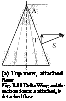
(i) Vortex lift: The additional lift generated by the sharp leading edge separation of highly swept wings at high angles of attack is called the vortex lift. This additional lift is calculated with the leading edge suction analogy and introduced by Polhamus (1971). This theory which is also validated by experiments is named Polhamus theory for the low aspect ratio delta wings. Now, let us analyze the generation of vortex lift with the aid of Fig. 1.10. According to the potential theory, the sectional lifting force was given in terms of the product of the density, free stream speed and bound circulation as in Eq. 1.1. We can resolve the lifting force into its chord wise component S and the normal component N. Here, S is the suction force generated by the leading edge portion of the upper surface of the airfoil. Accordingly, if the angle of attack is a then the suction force S = p U Г sina. Now, let us denote the effective circulation and the effective span of the delta wing, shown in Fig. 1.11, Г and h respectively. Here, we define the effective span as the length when multiplied with the average sectional lift that gives the total lifting force of the wing. This way, the total suction force of the wing becomes as

Подпись: I

(b) perspective view, detached flow

image14
Подпись: (a) Top view, attached flow Fig. 1.11 Delta Wing and the suction force: a attached, b detached flow

simple as Sh. Because of wing being finite, there is an induced drag force which opposes the leading edge suction force of the wing.

Accordingly, the thrust force T in terms of the leading edge suction and the down wash w, reads T = p Г h (U sina-w;). Let us define a non dimensional coefficient Kp emerging from potential considerations in terms of the area A of the wing,

Kp = 2 Г h /(A Usina)

Modern Topics
The total thrust coefficient can be expressed as

In Eq. 1.33, at the low angles of attack the potential contribution and at high angles of attack the vortex lift term becomes effective. For the low aspect ratio wings at angles of attack less than 10o, the total lift coefficient given by Eq. 1.11 is proportional to the angle of attack. Similarly, Eq. 1.33 also gives the lift coeffi­cient proportional with the angle of attack at low angles of attack.

For the case of low aspect ratio delta wings as shown in Fig. 1.11 if the angle of attack is further increased, the symmetry between the two vortices becomes spoiled. As a result of this asymmetry, the suction forces at the left and at right sides of the wing become unequal to create a moment with respect to the wing axes. This none zero moment in turn causes wing to rock along its axes.

(ii) Wing-Rock: The symmetry of the leading edge vortices for the low aspect ratio wings is sustained until a critical angle of attack. The further increase of angle of attack beyond the critical value for a certain wing or further reduction of the aspect ratio causes the symmetry to be spoiled. This in turn results in an almost periodic motion with respect to wing axis and this self induced motion is called wing-rock. The wing-rock was first observed during the stability experiments of delta wings performed in wind tunnels and then was validated with numerical investigations. During 1980s the vortex lattice method was extensively used to predict the wing-rock parameters for a single degree of freedom in rolling motion only. After those years however, two more degrees of freedom, displacements in vertical and span wise directions, are added to the studies based on Euler solvers. The Navier-Stokes solvers are expected to give the effect of viscosity on the wing – rock. The basics of wing-rock however, are given with the experimental data. Accordingly, the onset of wing-rock starts for the wings whose sweep angle is more than 74o (Ericksson 1984). For the wings having less then 74o sweep angle, instead of asymmetric vortex roll up, the vortex burst occurs at the left and right sides of the wing. In Fig. 1.12, the enveloping curve for the stable region, wing – rock and the vortex burst are given as functions of the aspect ratio and the angle of attack. The leading edge vortex burst causes a sudden suction loss at one side of the wing which causes a dynamic instability called roll divergence (Ericksson

Подпись: Fig. 1.12 The enveloping curve for the wing-rockПодпись:Подпись:Подпись: 2.0image15AR

1984). After the onset of roll divergence, the wing starts to turn continuously around its own axis.

Let us now give the regions for the wing-rock, vortex burst and the 2-D sep­aration in terms of the aspect ratio and the angle of attack by means of Fig. 1.12.

The information summarized in Fig. 1.12 also includes the conventional aerodynamics region for fixed wings having large aspect ratios.

The effect of roll angle and its rate on the generation of roll moment will be given in detail in later chapters.

(iii) Flapping wing theory (ornithopter aerodynamics): The flight of birds and their wing flapping to obtain propulsive and lifting forces have been of interest to many aerodynamicists as well as the natural scientists called ornithologists. After long and exhausting years of research and development only recently the proto­types of micro air vehicles are being flown for a short duration of experimental flights (Mueller and DeLaurier 2003). In this context, a simple model of a flight tested ornithopter prototype was given by its designer and producer (DeLaurier 1993).

The overall propulsive efficiency of flapping finite wing aerodynamics, which is only in vertical motion, was first given in 1940s with the theoretical work of Kucheman and von Holst as follows

1

g = TTI/AR (134)

Although their approach was based on quasi steady aerodynamics, according to Eq. 1.34 the efficiency was increasing with increase in aspect ratio. As we have stated before, the quasi steady aerodynamics is valid for the low values of the reduced frequency. This is only possible at considerably high free stream speeds. Because of speed limitations and geometry, the reduced frequency values must be greater than 0.3, which makes the unsteady aerodynamic treatment necessary. If the unsteady aerodynamics is utilized, with the leading edge suction the propulsion efficiency becomes inversely proportional with the reduced frequency. For the vertically flapping thin airfoil the efficiency value is 90% for k = 0.07 and becomes 50% as k approaches infinity (Garrick (1936)). Using the Garrick’s model for pitching and heaving-plunging airfoil, with certain phase lag between two degrees of freedom, it is possible to evaluate the lifting and the propulsive forces by means of strip theory. In addition, if we impose the span wise geometry and the elastic behavior of the wing to include the bending and torsional deflections, necessary power and the flapping moments are calculated for a sustainable flight (DeLaurier and Harris 1993). While making these calculations, the dynamic stall and the leading edge separation effects are also considered. The progress made and the challenges faced in determining the propulsive forces obtained via wing flapping, including the strong leading edge separation studies, are summarized in an extensive work of Platzer et al. (2008) Exactly opposite usage of wing flapping in a pitch-plunge mode is for the purpose of power extraction through efficient wind milling. The relevant conditions of power extraction via pitch-plunge

oscillations are discussed in a detail by Kinsey and Dumas (2008). More detailed information on proper applications of wing flapping will be given in the following chapters.

The Piston Theory

The piston theory is an approximate theory which works for thin wings at high speeds and at small angles of attack. If the characteristic thickness ratio of a body is s and Ms is the hypersonic similarity parameter then for Ms ^1 the Newtonian impact theory works well. For the values of Ms < 1 the piston theory becomes applicable. Since s is small for thin bodies, at high Mach numbers the shock generated at the leading edge is a highly inclined weak shock. This makes the flow region between the surface and the inclined shock a thin boundary layer attached to the surface. If the surface pressure at the boundary layer is p and the vertical velocity on the surface is wa, then the flow can be modeled as the wedge flow as shown in Fig. 1.9.

The piston theory is based on an analogy with a piston moving at a velocity w in a tube to create compression wave. The ratio of compression pressure created in the tube to the pressure before passing of the piston reads as (Liepmann and Roshko 1963; Hayes and Probstien 1966)

Подпись: у — 1 wПодпись: (1.30)Подпись: 1_P_

Подпись: api

Here, ax is the speed of sound for the gas at rest. If we linearize Eq. 1.30 by expanding into the series and retain the first two terms, the pressure ratio reads as

— ffi 1 + у— (1.31)

pi ai

Подпись: Wa Подпись: 0 Za 8 Za 0 t + 0 X Подпись: (1.32)

Wherein, wa is the time dependent vertical velocity which satisfies the following condition: wa ^ аж. The expression for the vertical velocity in terms of the body motion and the free stream velocity is given by

Подпись: Fig. 1.9 Flow over a wedge for the piston theory Подпись: M>1 ►
image12

Equation 1.31 is valid only for the hypersonic similarity values in, 0 < Ms < 0.15, and as long as the body remains at small angles of attack during the motion while the vertical velocity changes according to Eq. 1.32. For higher values of the

hypersonic similarity parameter, the higher order approximations will be provided in the relevant chapter.

Hypersonic Aerodynamics

According to Newtonian impact theory, which fails to explain the classical lift generation, the pressure exerted by the air particles impinging on a surface is equal to the time rate of change of momentum vertical to the wall. Using this principle we can find the pressure exerted by the air particles on the wall which is inclined with free stream with angle 0w. Since the velocity, as shown in Fig. 1.8, normal to the wall is Un the time rate of change of momentum becomes p = q Ц).

Подпись: p - Pi 2 q»u2 Подпись: 2 sin2 dw Подпись: 2 у M2 Подпись: (1.26)
Подпись: cp

If we write Un = U sin 0w, the surface pressure coefficient reads as

Подпись: M, UПодпись: U иimage11"Fig. 1.8 Velocity compo­nents for the impact theory

The free stream Mach number M is always high for hypersonic flows. There­fore, its square M2 ^ 1 is always true. If the wall inclination under consideration is sufficiently large i. e. hw is greater than 35o-40o, the second term in Eq. 1.26 becomes negligible compared to the first term. This allows us to obtain a simple expression for the surface pressure at hypersonic speeds as follows

Cp ffi 2 sin2 0W (1-27)

Now, we can find the lift and the drag force coefficients for hypersonic aero­dynamics based on the impact theory. According to Fig. 1.8 the sectional lift coefficient reads as

cl = 2 sin2 hw cos 0w, (1-28)

and the sectional drag coefficient becomes

cd = 2 sin3 hw (1-29)

Starting with Newton until the beginning of twentieth century, the lifting force was unsuccessfully explained by the impact theory. Because of sin2 term in Eq. 1.28 there was never sufficient lift force to be generated in small angles of attack. For this reason, even though Eq. 1.28 has been known since Newton’s time, it is only valid at hypersonic speeds and at high angles of attack. The drag coef­ficient expressed with Eq. 1.29, gives reasonable values at high angles of attack but gives small values at low angles of attack. We have to keep in mind that these formulae are obtained with perfect gas assumption.

The real gas effects at upper levels of atmosphere at hypersonic speeds play a very important role in physics of the external flows. At high speeds, the heat generated because of high skin friction excites the nitrogen and oxygen molecules of air to release their vibrational energy which increases the internal energy. This internal energy increase makes the air no longer a calorically perfect gas and therefore, the specific heat ratio of the air becomes a function of temperature. At higher speeds, when the temperature of air rises to the level of disassociation of nitrogen and oxygen molecules into their atoms, new species become present in the mixture of air. Even at higher speeds and temperatures, the nitrogen and oxygen atoms react with the other species to create new species in the air. Another real gas effect is the diffusion of species into each other. The rate of this diffusion becomes the measure of the catalyticity of the wall. At the catalytic walls, since the chemical reactions take place with infinite speeds the chemical equilibrium is established immediately. Because of this reason, the heat transfer at the catalytic walls is much higher compared to that of non-catalytic walls.

For a hypersonically cruising aerospace vehicle, there exists a heating prob­lem if it is slender, and low lift/drag ratio problem if it has a blunt body. The solution to this dilemma lies in the concept of ‘wave rider’. The wave rider
concept is based on a delta shaped wing which is immersed in a weak conic shock of relevant to the cruising Mach number. Necessary details will be given in following chapters.

Slender Body Aerodynamics

Munk-Jones airship theory is a good old useful tool for analyzing the aerodynamic behavior of slender bodies at small angles of attack even at supersonic speeds. The cross flow of a slender wing at a small angle of attack is approximately incompressible. Therefore, according to the Newton’s second law of motion, during the vertical motion of a slender body, the vertical momentum change of the air parcel with constant density displaced by the body motion is equal to the dif­ferential force acting on the body. Using this relation, we can decide on the aerodynamic stability of the slender body if we examine the sign of the

Fig. 1.7 Vertical forces act­ing on the slender body at angle of attack a

Подпись: U ( a'Подпись: L(x)Подпись: L(x)Подпись: Zaimage10

Подпись: dL dx Подпись: sdza dx Подпись: (1.25)

aerodynamic moment about the center of gravity of the body. Expressing the change of the vertical force L, as a lifting force in terms of the cross sectional are S and the equation of the axis z = za(x) of the body we obtain the following relation

In Fig. 1.7, shown are the vertical forces affecting the slender body whose axis is at an angle of attack a with the free stream direction. Note that the vertical forces are non zero only at the nose and at the tail area because of the cross sectional area increase in those regions. Since there is no area change along the middle portion of the body, there is no vertical force generated at that portion of the body.

As we see in Fig. 1.7, the change of the moment with angle of attack taken around the center of gravity determines the stability of the body. The net moment of the forces acting at the nose and at the tail of the body counteracts with each other to give the sign of the total moment change with a. The area increase at the tail section contributes to the stability as opposed to the apparent area increase at the nose region.

Compressible Unsteady Aerodynamics

The evaluation methods for the sectional as well as the total lift and moment coefficients for unsteady subsonic and supersonic flows will be given in Chap. 5. It is, however, possible to obtain approximate expressions for the amplitude of the sectional lift coefficients at high reduced frequencies and at transonic regimes where M approaches to unity as limiting value. For steady flow on the other hand, the analytical expression is not readily available since the equations are nonlinear. However, local linearization process is applied to obtain approximate values for the aerodynamic coefficients.

Now, we can give the expression for the amplitude of the sectional lift coef­ficient for a simple harmonically pitching thin airfoil in transonic flow

h « 4 (1 + ik)a, k > 1 (1.23)

Here, a is the amplitude of the angle of attack. Let us consider the same airfoil in a vertical motion with amplitude of h.

hl« 8 ikh/b, k > 1 (1.24)

All these formulae are available from (Bisplinghoff et al. 1996).

Aerodynamic response to the arbitrary motion of a thin airfoil in transonic flow will be studied in Chap. 5 with aid of relevant unit response function in different Mach numbers.

Unsteady Aerodynamics of Slender Wings

It is also customary to start the unsteady aerodynamic analysis of wings with simple harmonic motion and obtain analytical expressions for the amplitude of the aerodynamic coefficients of the large aspect ratio wings which have elliptical span wise load distribution. In addition, Reissner’s approach for the large aspect ratio rectangular wings numerically provides us with the aerodynamic characteristics. As a more general approach, the doublet lattice method handles wide range of aspect ratio wings with large sweeps and with span wise deflection in compressible subsonic flows. In later chapters, the necessary derivations and representative examples of these methods will be provided.

1.1 Compressible Steady Aerodynamics

It is a well known fact that at high speeds comparable with the speed of sound the effect of compressibility starts to play an important role on the aerodynamic characteristics of airfoil. At subsonic speeds, there exists a similarity between the compressible and incompressible external flows based on the Mach number M = U/аж, аж = free stream speed of sound. This similarity enables us to express the compressible pressure coefficient in terms of the incompressible pressure coefficient as follows

Подпись:Po

Подпись: o image7

Fig. 1.4 Prandtl-Glauert transformation, before M = 0, and after M = 0

Here,

Unsteady Aerodynamics of Slender Wings Подпись: 2 Pec U2

o

is the surface pressure coefficient for the incompressible flow about a wing which is kept with a fixed thickness and span but stretched along the flow direction, x, with the following rule

Подпись: (1.14)x

xo = — ; yo = y, Zo = z

1 – M2

as shown in Fig. 1.4. The Prandtl-Glauert transformation for the wings is sum­marized by Eq. 1.14 and Eq. 1.13 is used to obtain the corresponding surface pressure coefficient. By this transformation, once we know the incompressible pressure coefficient at a point x, y, z, Eq. 1.13 gives the pressure coefficient for the known free stream Mach number at the stretched coordinates xo, yo, zo. As seen from Fig. 1.4, it is not practical to build a new plan form for each Mach number. Therefore, we need to find more practical approach in utilizing Prandtl-Glauert transformation.

Unsteady Aerodynamics of Slender Wings Unsteady Aerodynamics of Slender Wings Подпись: (1.15a, b)

For this purpose, assuming that the free stream density does not change for the both flows, we integrate Eq. 1.13 in chord direction to obtain the same sectional lift coefficient for the incompressible and compressible flow. While doing so, if we keep the chord length same, i. e., divide xo with (1-M2)1/2, then the compressible sectional lift coefficient cl and moment coefficient cm become expressible in terms of the incompressible clo and cmo as follows

The result obtained with Eq. 1.15a, b is applicable only for the wings with large aspect ratios and as the aspect ratio gets smaller the formulae given by 1.15 a, b fails to give correct results. For two dimensional flows Eq. 1.15a, b gives good results before approaching critical Mach numbers. The critical Mach number is the free stream Mach number at which local flow on the airflow first reaches the speed of sound. Equations 1.15a, b are known as the Prandtl-Glauert compressibility correction and they give the compressible aerodynamic coefficients in terms of the Mach number of the flow and the incompressible aerodynamic coefficients. The drag coefficient, on the other hand, remains the same until the critical Mach number is reached.

Подпись: CL Подпись: AR ao— a 1 - M2AR + 2 Подпись: (1.16)

The total lift coefficient for the finite thin wings with the sectional lift slope ao, and aspect ratio AR reads as

Formula 1.16 is applicable until the critical Mach number is reached at the surface of the wing.

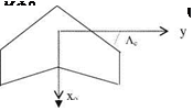
In case of finite wings, there is a way to increase the critical Mach number by giving sweep at the leading edge. If the leading edge sweep angle is Л, then the sectional lift coefficient at angle of attack which is measured with respect to the free stream direction, reads as

Подпись: (1.17)ao cos Л

— a

1 — M2 cos2 Л

Unsteady Aerodynamics of Slender Wings Unsteady Aerodynamics of Slender Wings Подпись: (1.18)

The effect of Mach number and the sweep angle combined reduces the sectional lift coefficient as compared to the wings having no sweep. Now, if we consider the aspect ratio of the finite wing, the Diederich formula becomes applicable for the total lift coefficient for considerably wide range of aspect ratios,

1 — M2

cos Ле = — cos Л.

1 — M2 cos2 Л

For the case of supersonic external flows, we encounter a new type of aerodynamic phenomenon wherein the Mach cones whose axes are parallel to the free stream send the disturbance only in downstream. The lifting pressure coefficient for a thin airfoil, in terms of the mean camber line z = za(x), reads as

image8"

Подпись: 4 dza pM2 - 1 dx Подпись: CPa Подпись: (1.19)

Fig. 1.5 Supersonic lifting pressure distributions along the flat plate

Figure 1.5 gives the lifting pressure coefficient distribution for a flat plate at angle of attack a.

In order to obtain the sectional lift for the flat plate airfoil we need to integrate Eq. 1.19 along the chord

Подпись: (1.20)4a

Pm2 – 1

Подпись: cm Подпись: 2 a a PM2 - 1 Unsteady Aerodynamics of Slender Wings Подпись: (1.21)

The sectional moment coefficient with respect to a point whose coordinate is a on the chord reads

Using Eqs. 1.20 and 1.21, the center of pressure is found at the half chord point as opposed to the quarter chord point for the case of subsonic flows. The effect of compressibility on the sectional lift coefficient is shown in Fig. 1.6 with the necessary modification near M = 1 area.

Подпись: Fig. 1.6 The change of the sectional lift coefficient with the Mach number. (The tran-sonic flow region is shown with dark lines, adopted from Kucheman (1978)) Unsteady Aerodynamics of Slender Wings Unsteady Aerodynamics of Slender Wings

An important characteristic of the supersonic flow is its wavy character. The reason for this is the hyperbolic character of the model equations at the supersonic speeds. The emergence of the disturbances with wavy character from the wing surface requires certain energy. This energy appears as wave drag around the airfoil. The sectional wave drag coefficient can be evaluated in terms of the equations for the mean camber line and the thickness distribution along the chord as follows.

1

Подпись: 'd_ dx* image9"Подпись: (1.22)Подпись: dx_—4

л/M2 – 1

-1

According to Eq. 1.22 the sectional drag coefficient is always positive and this is in agreement with the physics of the problem.

Steady Aerodynamics of Thin Wings

The finite wing aerodynamics, for special wing geometries, can yield analytical expressions for the aerodynamic coefficients in terms of the sectional properties of the wing. A special case is the elliptical span wise loading of the wing which is proportional to Jl2 — y2, where y is the span wise coordinate and l is the half span. For the wings with large span, using the Prandtl’s lifting line theory the wing’s lift coefficient CL becomes equal to the constant sectional lift coeffi­cient C[. Hence,

Cl = ci (1.9)

Подпись: CD Steady Aerodynamics of Thin Wings Подпись: (1.10)

Another interesting aspect of the finite wing theory is the effect of the tip vortices on the overall performance of the wing. The tip vortices induce a vertical velocity which in turn induces additional drag on the wing. Hence, the total drag coefficient of the wing reads

Here the aspect ratio is AR = l2/S, and S is the wing area. For the symmetric and untwisted wings to have elliptical loading the plan form geometry also should be elliptical as shown in Fig. 1.3.

For the case of non-elliptical wings, we use the Glauert’s Fourier series expansion of the span wise variation of the circulation given by the lifting line theory. The integration of the numerically obtained span wise distribution of the circulation gives us the total lift coefficient.

Подпись: Fig. 1.3 Elliptical plan form image4,image5 Подпись: > y

If the aspect ratio of a wing is not so large and the sweep angle is larger than 15o, then we use the Weissenger’s L-Method to evaluate the lift coefficient of the wing.

For slender delta wings and for very low aspect ratio slender wings, analytical expressions for the lift and drag coefficients are also available. The lift coefficient for a delta wing without a camber in spanwise direction is

Подпись: (1.11)CL = — n AR a

The induced drag coefficient for delta wings having elliptical load distribution along their span is given as

Подпись: (1.12)Co, = Cl a/2

The lift and drag coefficients for slender delta wings are almost unaffected from the cross flow. Therefore, even at high speeds the cross flow behaves incom­pressible and the expressions given by Eqs. 1.11-1.12 are valid even for the supersonic ranges. In Chap. 4, the Weissenger’s L-Method and the derivation of Eqs. 1.11-1.12 will be seen in a detail.

Unsteady Lifting Force Coefficient

During rapidly changing unsteady motion of an airfoil the aerodynamic response is no longer the timewise slightly changing steady phenomenon.

For example, let us consider a thin airfoil with a chord length of 2b undergoing a vertical simple harmonic motion in a free stream of U with zero angle of attack.

If the amplitude of the vertical motion is h and the angular frequency is ю then the profile location at any time t reads as

Za (t) = heix t (1.5)

If we implement the pure steady aerodynamics approach, because of Eq. 1.3 the sectional lift coefficient will read as zero. Now, we write the time dependent sectional lift coefficient in terms of the reduced frequency k = xb/U and the non­dimensional amplitude h* = h/b.

cl(t) = [-2 ikC(k)h* + k2h* ] л eix г (1.6)

Let us now analyze each term in Eq. 1.6 in terms of the relevant aerodynamics.

(i) Unsteady Aerodynamics: If we consider all the terms in Eq. 1.6 then the analysis is based on unsteady aerodynamics. C(k) in the first term of the expression is a complex function and called the Theodorsen function which is the measure of the phase lag between the motion and aerodynamic response. The second term, on the other hand, is the acceleration term based on the inertia of the air parcel displaced during the motion. It is called the apparent mass term and is significant for the reduced frequency values larger than unity.

(ii) Quasi Unsteady Aerodynamics: If we neglect the apparent mass term in Eq. 1.6 the aerodynamic analysis is then called quasi unsteady aerodynamics. Accordingly, the sectional lift coefficient reads as

cl(t) = [ —2лikC(k)h*] eix‘ (1.7)

Since the magnitude of the Theodorsen function is less than unity for the values of k larger than 0, quasi unsteady lift coefficient is always reduced. The Theodorsen function is given in terms of the Haenkel functions. An approximate expression for small values of k is: C(k) ffi 1 — л k/2+ ik(ln(k/2) + .5772), 0.01 < k < 0.1.

(iii) Quasi Steady Aerodynamics: If we take C(k) = 1, then the analysis becomes a quasi steady aerodynamics to give

cl(t) = [—2 лikh*] eix‘ (1.8)

In this case, there exists a 90o phase difference between the motion and the aerodynamic response.

(iv) Steady Aerodynamics: Since the angle of attack is zero, we get zero lift!

So far, we have seen the unsteady aerodynamics caused by simple harmonic airfoil motion. When the unsteady motion is arbitrary, there are new functions involved to represent the aerodynamic response of the airfoil to unit excitations. These functions are the integral effect of the Theodorsen function represented by infinitely many frequencies. For example, the Wagner function gives the response

to a unit angle of attack change and the Kussner function, on the other hand, provides the aerodynamic response to a unit sharp gust.

Generation of Lift

The very basic theory of aerodynamics lies in the Kutta-Joukowski theorem. This theorem states that for an airfoil with round leading and sharp trailing edge immersed in a uniform stream with an effective angle of attack, there exists a lifting force proportional to the density of air q, free stream velocity U and the circulation Г generated by the bound vortex. Hence, the sectional lifting force I is equal to

I = q U Г (1.1)

Figure 1.1 depicts the pertinent quantities involved in generation of lift.

The strength of the bound vortex is given by the circulation around the airfoil, Г = H Vds.

If the effective angle of attack is a, and the chord length of the airfoil is c = 2b, with the Joukowski transformation the magnitude of the circulation is found as Г = 2 pa b U. Substituting the value of Г into Eq. 1.1 gives the sectional lift force as

I = 2 qpabU2 (1.2)

Using the definition of sectional lift coefficient for the steady flow we obtain,

I, ,

image2 Подпись: stagnation streamline К

c = JUb = 2 pa (1:3)

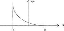
Fig. 1.2 Lifting surface pressure coefficients cpa: theoretical (solid line) and experimental (dotted line)

image3"The very same result can be obtained by integrating the relation between the vortex sheet strength ya and the lifting surface pressure coefficient cpa along the chord as follows.

cpa (x) cpl cpu 2Уа (x) = U

The lifting pressure coefficient for an airfoil with angle of attack reads as

b — x

cpa(x) = 2 a, — b < x < b (1.4)

b + x

Equation 1.4 is singular at the leading edge, x = —b, as depicted in Fig. 1.2. Integrating Eq. 1.4 along the chord and non-dimensionalizing the integral with b gives Eq. 1.3. The singularity appearing in Eq. 1.4 is an integrable singularity which, therefore, gives a finite lift coefficient 1.4. In Fig. 1.2, the comparisons of the theoretical and experimental values of lifting pressure coefficients for a thin airfoil are given. This comparison indicates that around the leading edge the experimental values suddenly drop to a finite value. For this reason, the experi­mental value of the lift coefficient is always slightly lower than the theoretical value predicted with a mathematical model. The derivation of Eq. 1.4 with the aid of a distributed vortex sheet will be given in detail in later chapters.

For steady aerodynamic cases, the center of pressure for symmetric thin airfoils can be found by the ratio the first moment of Eq. 1.1 with the lifting force coef­ficient, Eq. 1.3. The center of pressure and the aerodynamic centers are at the quarter chord of the symmetrical airfoils.

Abbot and Von Deonhoff give the geometrical and aerodynamic properties of so many conventional airfoils even utilized in the present time.

Unsteady Aerodynamics

If the motion of the profile or the wing in a free stream changes by time, so do the acting aerodynamic coefficients. When the changes in the motion are fast enough, the aerodynamic response of the body will have a phase lag. For faster changes in the motion, the inertia of the displaced air will contribute as the apparent mass term. If the apparent mass term is negligible, this type of analysis is called the quasi-unsteady aerodynamics.

1.1.5 Compressible Aerodynamics

When the free stream speeds become high enough, the compressibility of the air starts to change the aerodynamic characteristics of the profile. After exceeding the speed of sound, the compressibility effects changes the pressure distribution so drastically that the center pressure for a thin airfoil moves from quarter chord to midchord.

1.1.6 Vortex Aerodynamics

A vortex immersed in a free stream experiences a force proportional to density, vortex strength and the free stream speed. If the airfoil or the wing in a free stream is modeled with a continuous vortex sheet, the total aerodynamic force acting can be evaluated as the integral effect of the vortex sheet. In rotary aerodynamics, the
returning effect of the wake vorticity on the neighboring blade can also be mod­eled with vortex aerodynamics. At high angles of attack, at the sharp leading edge of highly swept wings the leading edge vortex generation causes such suction that it generates extra lift. Further angle of attack increase causes asymmetric gener­ation of leading edge vortices which in turn causes wing rock. The sign of the leading edge vortices of unswept oscillating wings, on the other hand, determines whether power or propulsive force generation, depending on the frequency and the center of the pitch. For these reasons, the vortex aerodynamics is essential for analyzing, especially the unsteady aerodynamic phenomenon.