Category HELICOPTER AERODYNAMICS

What determines the minimal vertical rate of descent during /140 helicopter gliding?

Answer 1. The vertical rate of descent descent during helicopter gliding is found from the formula V^eg = V ^ sin 0, i. e., it depends on the velocity along the trajectory and the gliding angle. The velocity along the trajectory depends on the forward or aft tilt of the coning axis. The gliding angle is determined by the lift force and depends on the main rotor pitch: the larger

the pitch, the larger the lift force, and the smaller the gliding angle and the vertical rate of descent.

G2Vgl

Подпись: descent is the propulsive force per unit

What determines the minimal vertical rate of descent during /140 helicopter gliding?

Answer 2. During helicopter gliding the vertical rate of found from the formula V^eg = V ^ sin 0. Since during a glide force is the weight force = G sin 0, the work of the weight time will be the equivalent power supplied to the rotor

What determines the minimal vertical rate of descent during /140 helicopter gliding? Подпись: N, What determines the minimal vertical rate of descent during /140 helicopter gliding? Подпись: N, Подпись: mm

Hence

Thus, the minimal vertical rate of descent in a glide depends on the flight weight and altitude. The gliding velocity along the trajectory should be equal to the economical speed for horizontal flight.

Main Rotor Cone of Revolution

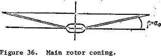
When horizontal hinges are used, the rotating rotor forms a "cone of revolution". If the flapping angle is positive, as the main rotor turns the blades travel along the generator of a cone whose apex is located at the center of the hub. The plane passing through the rotating rotor blade tips is called the main rotor plane of rotation [tip path plane] (Figure 36).

The line passing through the center of the hub perpendicular to the tip path plane is called the coning axis. The main rotor thrust vector passes lies along the coning axis.

Main Rotor Cone of RevolutionIf the blade flapping angle does not change azimuthally, the main rotor tip path plane is parallel to the hub rotation plane and the coning axis coincides with the main rotor hub axis. In this case the flapping angle 3 equals the coning angle a^. The coning angle is the angle a^ between the hub rotation plane and the generator of the cone of revolution. It varies from 0° to 10 – 12°.

The coning angle is larger, the larger the main rotor pitch. In – /53

crease of the pitch leads to increase of the blade thrust and moment about the horizontal hinge.

The main rotor cone of revolution is clearly visible if all the blades have the same flapping angle, i. e., there exists so-called co-conicity of the blades, absence of which leads to severe vibration of the main rotor. To obtain co-conicity it is necessary that the incidence angles of all the blades be the same. The technique for adjusting the rotor for blade tracking is given in the helicopter maintenance instructions.

Vertical Rate of Climb

Vertical Rate of Climb

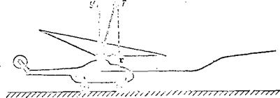
During climb the helicopter center of gravity moves along the flight trajectory with the velocity V The climbing velocity vector can be repre­sented as the vector sum

where is the horizontal component of the velocity;

V is the vertical rate of climb.

У

The horizontal component of the velocity equals V ^ cos 0, but since the climb angle is usually small and does not exceed 10°-12°, then ^ V^.

This means that the same power is expended on horizontal displacement of the helicopter during climb as is expended in horizontal flight at the same speed.

Analyzing (32) from this viewpoint, we can say that the excess power AN = GVy is expended on vertical displacement of the helicopter. Hence, knowing the helicopter weight and the excess power, we find the vertical rate of climb

Vertical Rate of Climb

The excess power can be found from the power required and available curves for helicopter horizontal flight (see Figure 63a). The maximal excess power corresponds to the economical speed (for the Mi-1, = 80 km/hr or

about 23 m/sec). Therefore, climbing should be performed at the economical speed. Moreover, from the power required and available curves for the Mi-1, we can conclude that vertical climb is impossible when using rated engine power. This means that the static ceiling when using rated power is equal to zero, i. e., helicopter hovering is possible only in the air cushion influence zone.

When using takeoff power vertical climb is possible, but the rate of climb will be lower than when climbing along an inclined trajectory. Conse­quently, this once again confirms that climbing should be performed along an inclined trajectory. Vertical climbing is performed only when it is necessary to clear surrounding obstacles. It must be kept in mind that takeoff power can be used only for a brief period, not to exceed five minutes.

Increase of the flight altitude involves change of the power required and the power available, and, therefore, change of the vertical rate of climb.

Dual-Rotor Helicopter Control Principles

Control principle of dual-rotor helicopter with tandem arrangement of the lifting rotors. Longitudinal control of the helicopter is achieved by
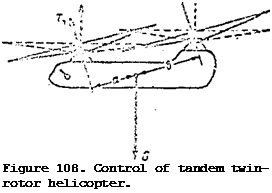
deflecting the stick fore and aft. This leads to cyclic change of the pitch of the lifting rotors, as a result of which the axes of the cones-of-rotation are tilted forward or backward, i. e., in the direction of the stick (Figure 108). In addition to the cyclic variation of the pitch there is a differential change of the collective pitch, in which the thrust of one rotor is increased while that of the other is decreased.

Подпись: v>Подпись: Figure 108. Control of tandem twin- rotor helicopter. If the stick is deflected forward, the axes of the cones-of- rotation of the lifting rotors are tilted forward. The collective pitch of the front rotor is reduced and that of the aft rotor is increased. As the thrust force vectors tilt, there is a change of the thrust force arms relative to the helicopter transverse axis. The result is the creation of a diving moment equal to the difference of the thrust moments of the front and rear rotors.

Under the influence of this moment the helicopter nose will drop, increasing the flight speed. If the stick is moved aft, a climbing moment is created and the helicopter nose will rise, reducing the flight speed.

Lateral control of the helicopter is achieved by deflecting the stick to the right and left. This leads to simultaneous identical change of the cyclic pitch of the front and rear lifting rotors. A lateral control moment appears which then causes rotation of the helicopter around the longitudinal axis.

Directional control, or control of helicopter rotation around the vertical axis, is accomplished with the aid of the directional control pedals. Deflection of the pedals leads to differential change of the cyclic pitch of the lifting rotors. The axes of the cones-of-rotation deflect in opposite directions, forming the directional control moment as a result of side forces. If the right pedal is pushed, the coning axis of the front rotor is deflected to the left. The side components of the lifting rotor thrust forces create a pair, whose moment turns the helicopter to the right.

Control principle of the dual-rotor helicopter with side-by-side lifting rotors. The control stick is moved fore and aft for longitudinal control, and this causes the same change of the cyclic pitch of the lifting rotors and deflection of the axes of the cones-of-revolution in the direction of stick displacement. This creates a longitudinal control moment (just as in the case of the single-rotor helicopter).

Lateral control is accomplished by deflecting the stick to the right or left. This deflection leads to differential change of the collective pitch of the lifting rotors. If the stick is moved to the right, the collective pitch of the right rotor is reduced and that of the left rotor is increased. Change of the collective pitch causes change of the thrust forces. The difference of the thrust forces of the right and left lifting rotors leads to the creation of a lateral moment which then causes a bank to the right.

The helicopter with side-by-side arrangement of the lifting rotors has an auxiliary wing which gives the helicopter lateral stability.

Directional control of the helicopter is accomplished by the control moment which is created by differential change of the cyclic pitch and tilting of the axes of the cones-of-rotation in opposite directions: forward and

backward. If the right pedal is pushed, the axis of the cone-of-rotation of the right rotor is deflected aft while that of the left is deflected forward. The horizontal components of the thrust forces create the directional control moment which causes rotation of the helicopter to the right.

Control principle of dual-rotor helicopter with coaxial rotors. Longi­tudinal and lateral control is accomplished similarly to the control of the single-rotor helicopter, i. e., by cyclic change of the pitch of the upper and lower lifting rotors. When the stick is deflected, the axes of the cones-of – rotation deflect in the same direction as the stick, creating the longitudinal or lateral control moment.

Directional control is accomplished by deflection of the pedals, which leads to differential change of the collective pitch of the lifting rotors.

This does not cause any change of the overall thrust, but leads to a change of the reactive moments of the lifting rotors and the helicopter turns in the direction of the action of the larger reactive moment.

Control of the vertical displacement of all helicopters is the same.

When the collective-throttle lever is moved up, the collective pitch of all the lifting rotors is increased, which leads to increase of the thrust and upward displacement of the helicopter. If the collective-throttle lever is fixed, the collective pitch is reduced, the thrust force decreases, and the helicopter transitions into descent.

Basic Regimes of Operation

The operating conditions of the main rotor or its working regime are defined as the position of the main rotor relative to the air stream. Depending

on the position, two basic working regimes are considered, those of axial and translational flow.

The axial flow regime is the term used for the operating condition of the main rotor where the axis of the hub is parallel to the oncoming free stream flow. In the axial flow regime the free stream passes perpendicular to the plane of rotation of the main rotor hub (Figure 12a). This regime covers the hovering, vertical climb and vertical descent conditions of the helicopter main rotor. An important feature of the axial flow regime is that the loca­tion of the blade of the rotor, relative to the oncoming free stream, is not changed. Consequently, the aerodynamic forces on the blade as it moves around the circle are not changed.

The oblique flow regime is the term used for the operating conditions of the main rotor, where the airstream approaches the rotor in a direction not parallel to the axis of the hub. An important difference of this regime is that, as the blade moves around in a circle, it continuously changes its location relative to the flow approaching the rotor. As a consequence, the velocity of the flow at each element is changed and also the aerodynamic forces on the blade. The translational flow regime occurs in the horizontal flight of a helicopter and in flight inclined upwards and downwards.

From consideration of the operating conditions, one can see that the position of the main rotor in the airflow is important. This position is determined by the angle of attack of the main rotor.

The angle of attack of the main rotor is termed angle A, and it is formed by the plane of rotation of the hub and the flight velocity vector, or by the undisturbed flow approaching the rotor. The angle of attack is positive if the flow approaches the rotor from below (Figure 12b). If the flow approaches the rotor from above, the angle of attack is negative (Figure 12c). If the airflow approaches the rotor parallel to the plane of rotation of the hub, the angle of attack is zero (Figure 12d).

а). •
A-ffO


. d) Г

A*ffe


CD

пз


b) A-Яв’


=£3


Basic Regimes of OperationBasic Regimes of Operation

Basic Regimes of Operation

Figure 12. Operating regimes and angle of attack of the main rotor.

It is not difficult to observe the connection between the operating regime of the main rotor and the angle of attack:

In the axial flow regime, the angle of attack of the main rotor A = + 90°. In the oblique flow regime, А Ф – 90°.

If the angle of attack A = 0°, the operating regime of the main rotor is termed the planar flow regime.

Blade Coriolis force and its azimuthal variation

Answer 1. The blade Coriolis force is the force which develops as a result of the combination of two velocities: the circumferential velocity of

the blade center of gravity and the radial velocity which develops as a result of variation of the flapping angle.

The Coriolis force of the advancing blade is directed in the direction of rotation of the motor and reaches its maximal value at the 90° azimuth.

The Coriolis force of the retreating blade is directed opposite the rotor rotation and reaches its maximal value at the 270° azimuth.

Answer 2. The Coriolis force is an inertial force which arises in the forward flight regime as a result of the combination of the circumferential velocity of the blade center of gravity and the helicopter translational flight velocity. For the advancing blade, this force is directed forward and reaches its maximal magnitude at the 90° azimuth; for the retreating blade it is directed aft and reaches its maximal value at the 270° azimuth.

Answer 3. The Coriolis force is an inertial force which arises from

Подпись: /73flapping motions resulting from the combination of the angular velocity of motion of the blade center of gravity and the vertical flapping velocity.

For the advancing blade, this force is directed upward and reaches its maximal value at the 90° azimuth; for the retreating blade, it is directed downward and will be maximal at the 270° azimuth.

Main Rotor Autorotation Conditions and Regimes

The main rotor blade element may be compared with an airplane wing element. Let us examine the aerodynamic forces acting on an airplane wing and then trans­fer these forces to the blade. The flight force Y and the drag force X develop on the airplane wing at the angle of attack a. The geometric sum of these forces will be the resultant aerodynamic force R = Y + X. The angle between the lift force Y and the resultant aerodynamic force R vectors is called the aerodynamic efficiency angle (0 ). The larger the aerodynamic efficiency angle, the lower the aerodynamic efficiency of the wing, since the minimal aerodynamic efficiency angle corresponds to maximal wing aerodynamic efficiency ctg 0 =

= Y/X = K. Reduction of the aerodynamic efficiency angle means a sort of "attraction" of the resultant aerodynamic force vector AR to the lift force vector Y, i. e., it means reduction of the backward tilt of AR relative to the normal to the undisturbed flow.

Main Rotor Autorotation Conditions and Regimes

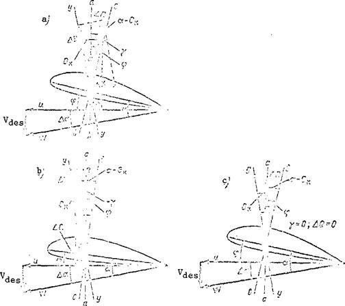
Figure 75. Blade element autorotati-ve conditions.

Now let us turn to examination of the forces acting on the blade. We draw three straight lines through the center of pressure of the blade element: a-а is perpendicular to the rotor rotation plane; b-Ъ is perpendicular to the blade element chord; y-y is perpendicular to the resultant velocity vector (Figure 75a). The angle between the lines y-y and b-b and the angle a are equal, since they are formed by mutually perpendicular sides. On this same basis, the angle between the lines a-a and b-Ъ is equal to the incidence angle ф.

The resultant aerodynamic force vector is applied at the blade element

center of pressure. We resolve this force into the lift force AY and the drag

force ДХ. The angle between the vectors AY and AR is the aerodynamic efficiency

angle The angle between the vector AR and the line b-b will be equal to

the difference of the angles (a – 0 ) . If this difference is less than the

blade incidence angle, then ф – (ot – 0 ) = у, i. e. , the angle у is positive. This

K.

means that the projection AQ of the force AR on the main rotor plane of rota­tion will be directed aft and creates a retarding moment which reduces the rotor rpm.

The main rotor will operate in the decelerated autorotative regime, which leads to stopping of the rotor. The larger the blade element incidence angle or pitch, the larger the angle y, and the larger the force AQ and its decelerating moment.

If the difference between the angle of attack and the aerodynamic effi­ciency angle is greater than the incidence angle, i. e., (a – 0 ) > ф, then

К

Ф – (a – 0„) = – y. The angle у is negative, which means that the vector AR /121

K.

is directed forward relative to the hub axis (Figure 75b). The projection AQ of the force AR on the hub rotation plane is directed forward and creates a turning moment which accelerates the rotor rotation. The main rotor will operate in the accelerated autorotative regime. The smaller the incidence angle ф, the larger the forward tilt of the vector AR, and the higher the speed at which the rotor turns.

If the difference (a – 0 ), then ф – (a – 0 ) = 0, i. e., the force AR is

К к

parallel to the hub axis and its projection on the hub rotation plane AQ = 0 (Figure 75c). In this case, the retarding or turning moment equals zero, and the rotor revolves at constant rpm, i. e., the rotor autorotative regime will be established.

From these examples we conclude:

— the tilt of the elemental resultant aerodynamic force vector depends on the blade element pitch;

— with reduction of the pitch, the force vector AR is deflected forward, and the main rotor autorotation becomes accelerated;

— with increase of the blade element pitch, the force vector AR is deflected aft, and the main rotor autorotation becomes decelerated.

The dependence of the autorotative regime on the blade element angle of

attack and pitch can be expressed graphically (Figure 76). This graph is

called the autorotation margin graph. The abscissa is the blade element

angle of attack, the ordinates are the incidence angles ф and the angles equal

to the difference a – 6 .

К

Let us examine the characteristic points in this figure. The ascending portion of this curve corresponds to blade element angles of attack below stall. The point В is the stall angle, and the descending portion corresponds to angles above stall.

If we draw a straight line paral­lel to the abscissa axis, it crosses the curve at the two points A and C.

In the figure, this straight line passes through the point on the ordinate corresponding to the incidence angle ф = 4° (such a straight line can be drawn through any point of the ordinate). What do the points A and C characterize? The point A corresponds to the blade element angle of attack (in our example a = 7°30′) which corresponds to steady state autorotation. Let us show that this actually is the case.

It was established above that steady state autorotation will occur when

the difference a – 0 = ф. In this case, the force AR of the element will be

К

parallel to the main rotor hub axis. In our example ф = 4° and а – 0^ = 4°. 180

This means that y= 0 (see Figure 75c). Therefore, in order for the Mi-1 helicopter blade to have steady state autorotation with ф = 4° the blade angle of attack must equal 7° 30′. Points of the curve for which Ct-0 <4 correspond to smaller angles of attack, i. e., the autorotation will be decelerated (see Figure 75a). At angles of attack between the points A and C all the points of the curve correspond to the inequality а-0^>ф, i. e., accelerated auto­rotation (see Figure 75b). But at angles of attack up to the stall angle, the accelerated autorotation will be stable, while at angles above stall flow separation takes place, and the autorotation is unstable.

The range of angles of attack between the points A and C is called the blade element autorotation margin. Since flight with blade element angles of attack above the stall angle is not feasible in practice, the autorotation margin will correspond to the angles of attack between the points A and in the figure.

With increase of the blade element pitch, the straight line AC shifts upward (A’C’). This means that the angle of attack range corresponding to decelerated autorotation increases, and the autorotation margin decreases.

With reduction of the pitch, the straight line AC shifts downward, and the autorotation margin increases.

Since the angles of attack are different for different blade elements, the autorotation conditions for these elements will also be different, and therefore the autorotation margin graph has a somewhat arbitrary nature, i. e., it serves for a qualitative evaluation of this process.

Let us return to the point A on the autorotation margin graph. In our example, it corresponds to ф = 4° and a= 7°30′. At these angles, the auto­rotation will be steady-state. But how can we obtain an angle of attack a = 7°30′ with an incidence angle ф = 4°?

Since а=ф+Да (see Figure 75b), then Да=а-4. This means that for our example the angle of attack increment caused by the vertical rate of

descent is &x=7°30,-4°=3°30′. Let us find the vertical rate of descent corresponding to this Да if r=0.7; ф=4°; ш=26 rad/sec. It is known that

If the vertical velocity < 7.9 m/sec, then for the given blade

element the angle of attack becomes less than 7°30′, and the autorotation will be decelerated;conversely, if > 7.9 m/sec, the autorotation will be

Подпись:accelerated. We must emphasize once again that the words "accelerated auto­rotation of the element" are arbitrary. They mean that under the given conditions the elemental resultant aerodynamic force vector AR is inclined forward relative to the hub axis and creates a turning moment. The larger the helicopter vertical rate of descent, the larger the angle of attack increment Да, the larger the forward tilt of the force vector AR, and the higher the main rotor rpm will be.

Characteristics of Operation of Coaxial System of Two Main Rotors

In the coaxial twin-rotor helicopter, the main rotors are positioned on a single axis — one above and the other below. Such a helicopter has certain operational characteristics. The area swept by the two main rotors is equal to the area swept by a single rotor

where Fc is the area swept by the system of coaxial rotors;

F^ is the area swept by a single rotor.

In this case, we have assumed that the diameters of the upper and lower /34

rotors are the same.

Let us examine the system of air jets passing through the areas swept by the upper and lower rotors (Figure 26). Increase of the distance between the hubs of the upper and lower rotors degrades the operating conditions of the lower rotor and complicates the construction of the entire system, while re­duction of this distance leads to the danger of collision of the rotor blades and increases helicopter vibration. This distance is h = 0.08D = 0.8m in the Ka-15 and Ka-18 helicopters. At this distance, the lower rotor has no effect on the operation of the upper rotor. The jet from the upper rotor con­tracts, and in the plane of rotation of the lower rotor its radius is 0.7R,

where R is the rotor radius. In this case, the lower rotor blade tips

operate under the same conditions as those of the upper rotor and draw additional air in from the side.

On this basis, we shall estimate the effective area of the entire system through which the air flows, just as for an isolated rotor in the hovering regime.

From the area swept by the upper rotor, we must subtract the root loss area (of radius 0.25R). Under conditions similar to those in the hovering regime, only the tips of the lower rotor blades operate. The area swept by these tips is

F ігтеЯ* _ тгО.72/?3.

1 V

Consequently, the effective area of both rotors through which the stream flows, as in the case of hovering of an isolated rotor, is found from the formula

Fc = *R2 _ *0.2S2/?2 + кГГ – – *0.7=i42 == 7гД* (1 _10.06 +

. +1 -0.49) = 1.45г,. ‘ ,

That portion of the lower rotor which operates in the jet of the upper rotor has lower efficiency. The angles of attack of the lower rotor blade elements are reduced as a result of the induced velocity of the upper rotor (see Figure 23b), which leads to reduction of the thrust. To reduce this effect, the incidence angles of the lower rotor blades are made 2-3° larger than for the upper rotor, but this does not eliminate entirely the harmful influence of the upper rotor on the lower. In the presence of this influence, the efficiency of the central portion of the lower rotor, which is in the jet from the upper rotor is reduced by a factor of two, in comparison with the efficiency of the tip area outside the jet from the upper rotor.

The swept area of the lower rotor, operating in the jet from the upper /35 rotor, is found from the formula

F± = kPFOJ2 – */?20.252 = = ^20.43-0.43Л.

Подпись:Подпись: iJ p p e r • main rotor Figure 26. Operation of coaxial rotor system. Since its efficiency is less than that of the upper rotor by a factor of two, the additional effective area of the lower rotor is
F = 0.43^0.5 = 0.22Fi.

e. 1 • –

The effective area of the entire

system isFe ^=lA5Fi–Q.22Fi = l.67Fi •

This formula shows that the thrust of

two coaxial rotors under the same conditions is greater than the thrust of an isolated main rotor of the same diameter by a factor of 1.67.

If the thrusts of the coaxial system and the isolated rotor are the same, then less power is required to create the thrust of the coaxial rotor system, which follows from ideal rotor momentum theory.

The power required to turn the ideal rotor is entirely converted into kinetic energy of the jet, i. e., N = TV^.

If we use Tc, Vc> F^, respectively, to denote the thrust, induced velocity, and effective area of the coaxial system of two rotors, and T^, V^, F^ to denote the thrust, induced velocity, and swept area of the isolated

rotor, then we have T = Tn.

5 cl

Characteristics of Operation of Coaxial System of Two Main Rotors

Consequently,

We know that

Fc = 1.67/7!.

Then

Hence, we find

T„ 2pFtVf V

Vc~ 2p 1.677?! = 1.67 ’

or

Characteristics of Operation of Coaxial System of Two Main Rotors0.78V!.

In order to obtain thrust on a system of coaxial rotors equal to the thrust of an isolated rotor of the same diameter, the induced velocity of the coaxial system must be less than the induced velocity of the isolated rotor.

Since the ideal rotor power required is proportional to 1Л, less power is required to obtain the same thrust for the coaxial system than for the /36

isolated rotor. This is the advantage of the coaxial system. The number

0. 78 ‘v is called the aerodynamic advantage coefficient, and is denoted by Using this coefficient, we express the power required for the coaxial system in terms of the power required of an isolated ideal rotor

This implies that for the same power the coaxial rotor system provides 13-15% more thrust than the isolated main rotor. Therefore, the helicopter with coaxial rotors has smaller dimensions than the single-rotor helicopter.

However, to date only light helicopters have been built using this scheme because of structural complexity and other problems.

Twin-rotor helicopters of other arrangements, for example, with the rotors placed longitudinally and with intermeshing rotors, also have an aerodynamic advantage in the axial flow regime. The aerodynamic advantage coefficient of these systems approaches closer to 0.8, the less the distance between the main rotor hub axes.

Thrust and Power Required. for Horizontal Flight

Подпись:

Подпись: YG Thrust and Power Required. for Horizontal Flight

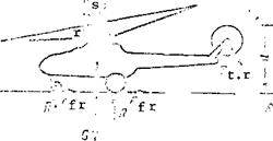
In horizontal flight the thrust force vector is tilted forward from the vertical and to the side in the direction of the retreating blade.

mation of the side force S = T,

s t. r

and the result of the forward tilt of the thrust force vector is the forma­tion of the propulsive force P = T sin у which pulls the helicopter forward,

overcoming the parasite drag. We recall that helicopter parasite drag is the resistance of all the nonlifting parts (other than the main rotor).

The projection of the thrust force on the vertical yields the lift force Y = T cos y. Therefore, to generate the lift and propulsive forces it is necessary to have the thrust force T^, which can be found from the force diagram (see Figure 59).

Thrust and Power Required. for Horizontal Flight(26)

Thrust and Power Required. for Horizontal Flight Подпись: /90

The thrust required for horizontal helicopter flight depends on its weight and parasite drag, which can be found from the formula

par

The parasite drag coefficient depends basically on the shape and attitude

of the fuselage, and also on the condition of its surface. The parasite drag

2

is proportional to the flight velocity squared, i. e., X ^ = f (V ).

With increase of the horizontal flight velocity the thrust required increases.

In horizontal flight there is a change not only of the magnitude of the thrust required, but also of its direction, i. e., the angle у of deflection of the thrust force vector from the vertical. Increase of the angle у is necessary in order to increase the propulsive force P while leaving the lift force Y unchanged.

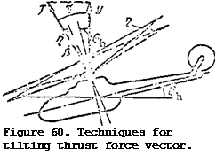
Tilt of the thrust force vector and increase of the angle are accomplished in three ways:

1) by deflecting the main rotor cone of revolution axis forward;

2) by tilting the helicopter forward;

3) by establishing the main rotor shaft at some angle g relative to the perpendicular to the fuselage structural axis (the line running along the fuselage), Figure 60.

Tilting the cone axis forward through the angle Г| is accomplished by deflecting the helicopter control stick forward. The main rotor cone axis tilts in the same direction in which the stick is deflected.

Tilting the entire helicopter through the angle 0^ (pitch angle) is accomplished by deflecting the control stick forward. The main rotor shaft

installation angle relative to the helicopter structural axis always remains the same.

Подпись:Thus, the thrust force vector forward tilt angle will be equal to

the sum of the angles Л» 3. The larger the angle y, the larger the propulsive force P, and the higher the helicopter speed.

The work which must be supplied to the main rotor shaft per unit time is called the power required for

Thrust and Power Required. for Horizontal Flight

Thrust and Power Required. for Horizontal Flight

helicopter horizontal flight. The power required is made up of three parts: [1] [2] [3]

Thrust and Power Required. for Horizontal Flight

Using (26a), we find the power required for motion of the Mi-1 helicopter (G = 2200 kgf, H = 0).

(continued)

37-20

75


И hp; 37 hp;

79 hp; 153 hp-


V = 20 m/sec; N

mot

V = 30 m/sec; N

mot

V = 40 m/sec; N

mot

V = 50 m/sec; N

mot


83-30

75


147-40

75


230-50

75


Thrust and Power Required. for Horizontal Flight

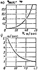
These values make it possible to plot a graph of the variation with

flight speed of the power required for motion of the helicopter (Figure 61a).

2

Since N and the parasite drag X = f (V ), the motion power required mot _ par

N = f (v) and increases more sharply with increase of the flight speed, mot

The average induced velocity for the main rotor of the Mi-1 helicopter decreases with increase of the horizontal flight speed (Figure 61b).

Using this figure and the Formula (27), we calculate the induced power,

i. e., the power expended in creating the helicopter lift force

Подпись: V=Q; 10 V — 20 Nt = -2-^- = 245 hP; m/sec: « -22(^,–5- = 147 hp;
– , дг 2:;00-!>,6 oc

m/sec; N і ——- ycj — OO hp1

From these results we can plot the induced power as a function of flight speed (Figure 61c) .

The reduction of the induced power with increase of the flight speed is explained by the fact that the rotor interacts with a larger mass of air ; therefore, less downwash is required to create a lift force equal to the /92

ч N, hp c) pr’ F

Подпись: a) Nmot’ hp 11:

cO

ад

ад із

V. m/sec

О 7.0 ад и

‘Л m/sec ‘•< m/sec

Figure 61. Power components versus flight speed.

helicopter weight. The power expended in overcoming profile drag increases with increase of the flight speed (Figure 61d). The increase of the profile power is explained by the increase of the air friction forces in the blade boundary layer with increase of the flow velocity over the blades. In the forward flight regime the flow relative velocity increases for the advancing blades (V7 = U + KsirHi-‘ > while it decreases for the retreating blades

Подпись: N. = N „ h mot Подпись: N. + і Подпись: prJ

— V Sini^), but since X = f (W^) the drag of the advancing blade increases more rapidly than the drag of the retreating blade decreases. After calculating the component parts of the power required, we find the power required for horizontal flight of the Mi-1 helicopter

V = 10 m/sec; = 4 + 147+ 140 = 291 hp;

V = 30 m/sec; Nh = 37 + 62 + 160 = 259 hp;

V = 50 m/sec; Nh = 153 + 42 + 180 = 375 hp.

Using these values, we plot the power required for horizontal flight as a function of the flight speed for the Mi-1 helicopter(H = 0; G = 2200 kgf)

(Figure 62). We see from this figure that with increase of the velocity from zero to 80 km/hr the power required for horizontal flight decreases. The speed for which the power required for horizontal flight is minimal is called the helicopter’s economical speed.

HELICOPTER TAKEOFF AND LANDING. Takeoff

Helicopter takeoff is an unsteady accelerated flight mode. During take­off the velocity varies from V = 0 to the velocity at which steady-state climb is established. This climbing speed is usually equal to the economical horizontal flight speed. Depending on takeoff weight, airfield altitude above sea level, and presence of obstacles, the takeoff may be performed helicopter-style, airplane-style, and helicopter-style with or without utilization of the "air cushion."

Sometimes the helicopter travels over the ground prior to or during takeoff, i. e., taxiing is performed. Helicopter taxiing differs significantly from airplane taxiing.

Helicopter taxiing characteristics. Taxiing is accomplished by means of the propulsive force P, which balances the wheel friction force F (Figure 87a). The reactive moment of the main rotor is balanced by the thrust moment of the tail rotor. The basic differences in helicopter taxiing are:

(1) Presence of a large lift force, which is a component of the main rotor thrust and reduces the wheel pressure force on the ground, i. e., reduces the support reaction. As a result, wheel friction on the ground is reduced, and the possibility of helicopter overturning is increased;

(2) Presence of side forces: tail rotor thrust and the side component

of the main rotor thrust (Figure 87b). These forces develop large overturning moments about the wheel support points, which balance one another. But if there is a change of one of the side forces the overturning moment is un­balanced and can cause the helicopter to overturn (Figure 87c);

(3)

Подпись: a) 4 Подпись: b) Подпись: c)

A large nose-down moment develops as a result of the propulsive force P, which creates high loads on the landing gear wheels (wheel).

Подпись:t. r

Подпись: /7-УПодпись: Figure 87. Forces acting on helicopter in taxiing.HELICOPTER TAKEOFF AND LANDING. Takeoff‘ t. rt? ,

/ї •?

Therefore, helicopter taxiing must be performed more carefully than airplane taxiing. The taxiing speed must not exceed 10 – 15 km/hr. The surface of the area over which taxiing is performed must be smooth. Taxiing in a strong crosswind is not permitted, since this can lead to overturning of the helicopter.

Helicopter-style takeoff is the primary takeoff mode (Figure 88). In this takeoff a vertical liftoff is made and check hovering is performed at a height of 1.5 -2m (operation of the main rotor, engine, and equipment is checked). Then the helicopter is transitioned into climb along an inclined trajectory with simultaneous increase of the speed. In this process "sinking"

HELICOPTER TAKEOFF AND LANDING. Takeoff

з


г


HELICOPTER TAKEOFF AND LANDING. Takeoff

HELICOPTER TAKEOFF AND LANDING. TakeoffHELICOPTER TAKEOFF AND LANDING. TakeoffHELICOPTER TAKEOFF AND LANDING. TakeoffHELICOPTER TAKEOFF AND LANDING. Takeoff

Figure 88. Helicopter-type takeoff.

of the helicopter is possible, i. e., a reduction of the altitude, and sometimes the wheels may even come in contact with the ground. This phenomenon is caused by tilting the main rotor coning axis forward to develop the propulsive force P, the result being a decrease of the vertical component of the main rotor thrust. Therefore, along with tilting of the main rotor coning axis forward, there must be an increase of the thrust force by increasing the rotor pitch.

Подпись: /142The takeoff is considered terminated when the helicopter reaches a height of 20 – 25 meters or is above the surrounding obstacles. At this time the acceleration, i. e., the increase of the velocity along the trajectory to the optimal climbing speed, which corresponds to the minimum level flight power, is also terminated. But this type of takeoff cannot he performed if:

the helicopter is overloaded (insufficient engine for hovering outside the "air cushion" influence zone);

the air temperature is high (reduced engine power);

the takeoff is made from a high-altitude airfield (low air density at the given altitude so that insufficient engine power is available). Under

these conditions an airplane-type takeoff is made.

Airplane-type takeoff. During the airplane-type takeoff the helicopter accelerates on the ground, then lifts off and transitions into a climb along an inclined trajectory (Figure 89). In this takeoff use is made of the pri­mary advantage of main rotor operation in the forward flight: increase of

the thrust developed by the rotor with increase of the velocity of the air stream approaching the main rotor (see Figure 68).

HELICOPTER TAKEOFF AND LANDING. Takeoff

Figure 89. Airplane-type takeoff.

As a result of the thrust increase there is an increase of the lift force. /143 When it becomes somewhat greater than the weight force, the helicopter lifts from the ground and transitions into a climb along an inclined trajectory with further increase of the flight speed. We see from the power required and available curves for horizontal flight (see Figure 63a) that the power required for horizontal flight decreases markedly for even a small speed increase. If takeoff is impossible at V = 0 because of insufficient power, at a speed of 40 – 50 km/hr considerable excess power is developed, which then makes it possible for the helicopter to transition to the climb regime with simultaneous increase of the flight speed.

An airfield or at least a small smooth area is required for the airplane – type takeoff. The ground run during takeoff with flight weight exceeding by

10 – 15% the normal takeoff weight for helicopter-type takeoff is 50 – 100 meters. In this case the liftoff speed is 50 – 70 km/hr (with acceleration during the ground run 2.2 m/sec ) and the ground run time is 7 – 10 seconds.

The ground run is performed on all wheels of the landing gear. Some helicopters (the Mi-6, for example) perform the last part of the ground run on the nosewheel. When using this ground run technique the acceleration is increased as a result of the inclination of the fuselage longitudinal axis and the resulting increase of the propulsive force P. The helicopter takeoff is considered complete when a safe height (25 m) and a velocity along the trajectory close to the economical speed for horizontal flight have been reached.

Helicopter-type takeoff utilizing the air cushion. Vibrations may arise during airplane-type takeoff ground run on an uneven surface. Then the take­off is made using the air cushion (Figure 90). In this takeoff the helicopter lifts off vertically, utilizing the increased main rotor thrust in the air cushion influence zone (the distance from the main rotor plane of revolution to the ground does not exceed R).

Подпись:After liftoff and hovering in the air cushion zone, the helicopter is transitioned into forward flight i. e., flight at low height with increase of the speed. During the transition maneuver the influence of the air cushion diminishes with increase of the speed, but the forward flight effectiveness increases; therefore, the main rotor thrust force increases, which makes it possible to transition the helicopter into a climb along an inclined trajec­tory. In order to perform such a takeoff it is necessary to have a sufficiently smooth area, i. e., there must not be any large ditches or dropoffs, where the influence of the air cushion disappears.

In certain cases none of the techniques examined above are applicable because of obstacles surrounding the area. Then takeoff is made without

utilization of the air cushion, i. e., liftoff and check hovering are performed and then a vertical climb is initiated. At a height of 5 – 10 meters above the surrounding obstacles the helicopter is transitioned into climb along an inclined trajectory with simultaneous acceleration to the economical velocity. Vertical takeoff is rarely used, since it requires high power and is performed in the danger zone. If sufficient power is not available, yet takeoff must be made, the helicopter weight should be reduced.