Category HELICOPTER AERODYNAMICS

Blade Flapping Motions

Blade motions relative to the main rotor hub horizontal hinges in the forward flight regime are called flapping motions. These motions arise when the blade equilibrium relative to the horizontal hinges is disrupted because of azimuthal variation of the blade thrust.

When the blade thrust and moment increase it flaps upward, and when the thrust and moment decrease it flaps downward. Let us see how the blade flapping

angles vary with azimuth.

For the advancing blade with ip from 0 to 90° the resultant flow velocity over the blade and the blade thrust and moment increase, and the blade flaps upward — the flapping angle and the vertical velocity increase. At the 90° azimuth the upward vertical flapping velocity reaches the maximal value.

For ip > 90° the blade thrust and vertical flapping velocity decrease, while the flapping angle continues to increase.

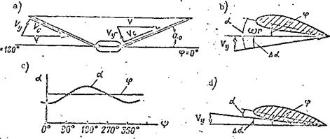
The blade flapping motions are affected not only by variation of the re­sultant velocity, hut also by variation of the blade element angle of attack caused by the main rotor coning angle. As a result of the coning angle the undisturbed stream approaches the blade located at the 180° azimuth at some angle from below, and approaches the blade located at the 360° azimuth at some angle from above (Figure 37a).

The undistrubed stream velocity vector can be broken down into the com­ponents: V perpendicular to the blade longitudinal axis, and Vg parallel to

the blade axis. The latter is called the slip velocity. The blade element

angle of attack and thrust are independent of V. At the 180° azimuth the

s

vector Vy is directed at the blade from below, consequently this leads to increase of the blade element angle of attack by the magnitude Да (Figure 37b).

The induced flow velocity is not shown in the figure.

At the 360° azimuth (Figure 37a) the vector is directed downward toward the blade, which leads to reduction of the blade element angle of attack (Figure 37d). Thus, as a result of coning the angle of attack of each blade element changes azimuthally from a maximum at the 180° azimuth to a minimum at the 360° azimuth. At the 90°and 270° azimuths, the angles of 1$A.

attack equal the incidence angle (without account for the induced velocity and the flapping motion velocity), Figure 37c.

Blade Flapping Motions

Figure 37. Blade element angle of attack as a function of main rotor coning angle.

But the increase of the blade element angle of attack as a result of the coning angle for ф > 90° leads to increase of the thrust and further upward flapping. As a result of this effect, the maximal blade flapping angle in the forward flight regime will occur at ф и 210°. In this case equilibrium of the blade relative to the horizontal hinge is established. As the blade motion continues around the circle, the blade thrust decreases as a result of reduction of the resultant velocity and the blade element angle of attack, and equilibrium is disrupted, i. e.,

MT<i MQ + MN.

The vertical downward flapping velocity will be maximal at the 270° azimuth. Equilibrium is reached again for ф 30° and the flapping angle will be minimal.

This variation of the flapping angle in azimuth is possible in the for­ward flight regime if the blade incidence angle does not change in azimuth and account is not taken of elastic twisting of the blade under the influence of the aerodynamic forces.

Variation of Vertical Rate of Climb with Altitude

If we calculate the power required for horizontal helicopter flight at various altitudes and construct curves of these powers, and if we find the power available at various altitudes from the engine altitude characteristics,

then we can use these curves to draw important conclusions on altitude variation of the helicopter flight characteristics.

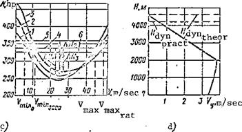
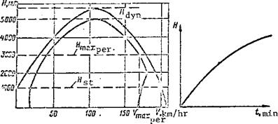
Let us examine such curves for the Mi-1 helicopter (Figure 69a). We see from the curves that:

1) for flight speeds less than optimal the power required curves are

shifted upward;

2) for flight speeds greater than optimal these curves are shifted

downward;

3) the power available lines shift upward up to the critical altitude of

2000 meters and then shift downward; this shift causes increase of the maximal speed up to the critical altitude and reduction at altitudes above critical;

4) there is an increase of the minimal speed and an initial increase and

subsequent decrease of the excess power (see Table). We obtained these data using rated engine power. If takeoff power is used, vertical climb can be performed up to an altitude of about 1000 m, and the maximal speed at sea level will be about 210 km/hr.

ALTITUDE VARIATION OF FLIGHT CHARACTERISTICS

H. M

^шзх»

kn/hr

^m’n»

-km/hr ‘

л N. .hn’

Vyt km/hr

0

166 ‘■

• 18

ICO

3,4

. 2000

ISO

25

110

3,8

3000

169 •

40

– 63

2,2

4000

‘ 150

. 58

30

1

The tabular data can be used to plot two graphs which characterize the helicopter flight characteristics:

Подпись: altitude dependence of altitude dependence ofthe vertical rate of climb; the maximal and minimal speeds.

Variation of Vertical Rate of Climb with Altitude

Variation of Vertical Rate of Climb with Altitude

Figure 69. Helicopter aerodynamic characteristics:

1,2,3- Nh; 4 – Navail for H = 0; 5 – for

H = 2000 m; 6 – N.. for H = 3000 m. avail

The plot of vertical rate of climb versus altitude (Figure 69b) shows that the vertical rate of climb increases up to the engine critical altitude. Above this altitude the rate of climb decreases.

The altitude at which the vertical rate of climb for flight along an inclined trajectory equals zero is called the helicopter dynamic ceiling.

More precisely, this altitude is called the theoretical dynamic ceiling.

Since the helicopter does not actually climb to this altitude, the practical

ceiling concept is introduced, at which the vertical rate of climb equals

0. 5 m/sec. The maximal and minimal speed plot (Figure 69c) shows the increase of the helicopter maximal horizontal flight speed with altitude increase from zero to the engine critical altitude. At altitudes above critical the maximal speed decreases. The minimal speed increases with increase of the altitude.

At the dynamic ceiling altitude, the helicopter can perform flight only at a single speed, which will be both maximal and minimal at the same time. During flight at altitudes less than the dynamic ceiling, the helicopter has a range of speeds in horizontal flight from minimal to maximal.

Figure 69c shows two curves: one of them corresponds to flight using

rated engine power ; the other corresponds to use of takeoff engine power. In the latter case, we see the helicopter static ceiling, i. e., the maximal altitude for helicopter hovering out of the air cushion effect.

The graph showing the variation of the maximal and minimal horizontal flight speeds as a function of altitude is called the helicopter aerodynamic "passport". This "passport" characterizes the helicopter flight data. In many cases, the flight characteristics have various limitations, which ensure structural strength or an acceptable vibration level. Thus, for the Mi-1 helicopter, the maximal flight speed must not exceed 170 km/hr at altitudes from 0 to 3000 meters.

Подпись: /108The ceiling of the Mi-1 is limited to an altitude of 3000 meters.

‘Xj

Record speeds for light helicopters (V = 210 km/hr and H ‘ь 6000 m) have been established during flight tests and in special flights on the Mi-1 helicopter.

If the vertical rate of climb is used to calculate the time to climb to various altitudes, we can plot the so-called climb barogram, which also characterizes the helicopter flight characteristics (Figure 69d).

Concept of Helicopter Controllability

Helicopter controllability refers to its ability to be rotated about its principal axes under the action of the control moments, which are created by deflection of the control command levers. The controllability is charac­terized by control effectiveness, control sensitivity, control lag, and the forces on the command levers.

Control effectiveness. By control effectiveness we mean the magnitude of the control moment per degree of deflection of the tilt control and per degree of change of the tail rotor pitch. Control effectiveness, and controllability as well, is divided into longitudinal, lateral, and directional. Longitudinal

м

control effectiveness is found from the ratio — of the longitudinal control

moment to the tilt control longitudinal deflection angle л. The lateral

control effectiveness is defined by the ratio (where x is the tilt control

X

transverse deflection angle). The directional control effectiveness is

M

found from the ratio _JSL (where Дф is the tail rotor pitch change) .

Дф

Longitudinal and lateral control effectiveness depends on tail rotor rpm, vertical location of the helicopter center of gravity, and horizontal hinge offset. The higher the main rotor rpm and the larger the blade thrust and centrifugal forces, the larger the longitudinal and lateral control moments and the greater the control effectiveness. For these reasons the main rotor rpm cannot be reduced markedly, since the control effectiveness decreases.

The lower the helicopter center of gravity, the larger the main rotor thrust arm relative to the center of gravity and the larger the control moment and the higher the effectiveness. This means that cargo should be located as low as possible in the helicopter.

In speaking of the deflection of the tilt control relative to the univer­sal axis, we must bear in mind that the deflection angles are severely limited and do not exceed л = 4 – 6° in the longitudinal direction and X < 4° in the lateral direction.

The longitudinal and lateral control effectiveness of the Mi-4 helicopter is

M M

——~—— «450 kgfm/deg. n X

Control sensitivity. Control sensitivity is equal to the ratio of the angular rate of rotation of the helicopter around any axis to the tilt control deflection angle. Lateral control sensitivity is usually greater than the

longitudinal and directional control sensitivities. The control sensitivity is usually greater for light than for heavy helicopters. The control sensi­tivity depends on the control effectiveness and the damping moment. The greater the control effectiveness, the higher the sensitivity; the larger the damping moment, the lower the control sensitivity.

Control lag. The control moment which leads to rotation of the helicopter about any axis (longitudinal or transverse) is created by main rotor thrust force vector deviation. A characteristic feature of these moments is the large magnitude of the thrust force and the small magnitude of the arm of this force relative to the axis of rotation. Consequently, in order to create a control moment we must impart to the large mass of air discharged by the main rotor additional momentum in a new direction in order to obtain a new direction of the thrust force. A comparatively long time is spent on this.

This time equals approximately the time for a single rotation of the main rotor and amounts to 0.2 – 0.3 seconds.

Consequently, this time is required for the helicopter to begin rotation

about the longitudinal or lateral axes after the control stick is displaced.

This is then the control lag. This lag will be longer, the larger the helicopter moment of inertia relative to the axis of rotation and the lower the main rotor rpm. The lag in the longitudinal control is greater than in

the lateral. For comparison we take the control lag for an airplane. The

airplane control moment is created by comparatively small forces with large arms. Therefore, the creation of the control moments for an airplane requires about one tenth of the time of that for a helicopter. This characteristic must be considered in helicopter piloting techniques.

Control stick force. An attempt is made to have the main rotor blades momentless. This means that with variation of the pitch the blade center of pressure shifts very little and the blade moment about its longitudinal axis scarcely changes at all. But small moment changes still arise. These varia­tions are transmitted through the pitch control horns to the blades, from the

blade to the tilt control, and from there to the cyclic pitch control lever. High-frequency force pulsations develop on the stick and it begins to vibrate.

To eliminate these vibrations, inertial or hydraulic dampers which absorb small blade oscillations are connected into the control linkage system.

In the inertial dampers the energy of the oscillatory motions is expended on rotating the pendulum, and in the hydraulic dampers on overcoming the friction forces of the piston and the fluid forced through the piston. Dampers in the control system are used on the light helicopters. Hydraulic boosters are used on the intermediate and heavy helicopters, which create mechanical /177 forces by fluid pressure on the hydraulic booster piston. These forces are used to deflect the tilt control or change the tail rotor pitch. Each control loop has its own hydraulic booster.

Irreversible boosters are most widely used at the present time; they can deflect the control organs without forces from the pilot. When moving the command lever, the pilot displaces only the slide valve piston, which regulates the fluid flowrate into the booster. Consequently, there are no forces at all on the command levers, i. e., the stick and pedals move without any resistance. This means that the pilot does not feel the helicopter control and cannot define exactly the magnitude of the command lever deflection.

In addition to the boosters, artifical feel mechanisms are provided in the helicopter control system to create definite forces on the stick to give a "control feel." These artificial feel units are provided in each control loop and consist of springs. When the command lever is deflected, one of these springs is compressed and pilot effort is expended in this compression.

The magnitude of the force increases as the stick is deflected. If these forces are applied for brief periods they do not create any serious inconven­ience (bearing in mind that the pilot very rarely deflects the stick fully to restore equilibrium). However, if it is necessary to alter the flight regime, for example to transition from hover to flight at maximal speed, then the stick must be moved nearly full forward and held in this position. In this

або

case the pilot must apply a large force to the stick for a long period. This soon causes fatigue. A trimming mechanism or a load-relieving mechanism is used to remove or regulate the force on the stick.

The Operating Regime Coefficient of the Main Rotor

A special quantity is introduced to characterize the operating regimes

(*)

of the main rotor — the operating regime coefficient

The operating regime coefficient of a main rotor, y, is defined as the ratio of the projection of the flight velocity vector on the plane of rotation of the hub to the circular velocity of the blade tip. The projection of the flight velocity vector, or the undisturbed flow, on the plane of rotation of the hub is equal to the product of V cos A (Figure 13).

The Operating Regime Coefficient of the Main Rotor

This is the tip speed ratio.


Подпись: V cos A Подпись: C3

Then we have

In the axial flow regime, when V = 0, or cos A = 0(A = 90°), у = 0.

Consequently, the equation у = 0 indicates the axial flow regime. If у > 0, this is the index of the trans­verse flow regime. The larger the coefficient y, the larger the effect of transverse flow. The coefficient у for contemporary helicopters varies from 0 to 0.4. In most cases the angle of attack of the main rotor does not exceed 10°. Since cos 10° as 1, then it is possible to define у by the approximate formula

V


HELICOPTER VERTICAL FLIGHT OPERATING REGIMES

Concept of helicopter flight regimes. The helicopter flight regime can be either steady state or nonsteady state. Rectilinear flight at constant velocity is termed a steady state regime. The steady-state regimes can be subdivided as follows.

1. Vertical flight regimes: hovering;

vertical climb; vertical descent.

There are two varieties of vertical descent: descent with engine

operating and descent in the main rotor autorotation regime.

2. Horizontal flight regime.

3. Climb regime along inclined trajectory.

4. Descent regime along inclined trajectory (can be performed with engine operating or with main rotor autorotating).

The unsteady flight regime is one in which the velocity vector changes in magnitude or direction. The unsteady regimes include takeoff, landing, maneuvering (horizontal turns, heading changes, spiral, snaking, and so on) and transition from one flight regime to another.

In accordance with the law of inertia, a body travels uniformly and rectilinearly or is in a state of rest if no external forces act on it. The steady-state flight regime is uniform, rectilinear motion of the helicopter. Consequently, for the realization of this regime it is necessary that the geometric sum of the forces acting on the helicopter in flight be equal to zero. Moreover, the sum of the force moments acting on the helicopter relative to the center of gravity must also he equal to zero. These will then be the conditions for complete equilibrium of the helicopter.

Unsteady flight can occur only if some unbalanced force acts on the helicopter and imparts an acceleration to it, i. e.,

EF ^ 0 and EM ^ 0. eg eg

Conditions for Autorotation of Different Blade Elements

We have examined above the conditions for rotor autorotation as a function of blade element pitch and angle of attack. To facilitate our understanding of the problem, we assumed that all the blade elements operate under the same conditions, i. e., all the elements have the same incidence angles, velocities, the same forces AR, and the same inclination of these forces. But in reality,

each blade element operates under different autorotation conditions. Let us examine these conditions.

The angle of attack increment Act depends not only on the vertical rate of descent, but also on the circumferential velocity of the blade element.

The circumferential velocity is considerably higher for the tip elements than for the root elements; therefore, the angle of attack increment of the tip element is less than that of the root element, i. e., Aa^ < Aa^ (Figure 77a).

But then the elemental force vectors AR for the tip elements are inclined aft because of the low value of Да and create retarding moments. The blade tip elements usually operate in the decelerated autorotation regime. The retarding action of the tip elements is reduced by geometric twist of the blade but is not eliminated entirely.

The value of Да will be large for the root elements; therefore, the elemental force vectors AR will be tilted forward, and their projections AQ provide a turning moment. Consequently, the blade root elements operate under accelerated autorotation conditions. Since the blade tip elements retard the rotation while the root elements accelerate the rotation, what will be the operating regime of the entire rotor?

With reduction of the rotor pitch and with increase of the vertical rate of descent, the retarding action of the tip elements is less than the acceler­ating action of the root elements. The resultant of the elementary forces is directed forward, in the direction of rotor rotation and forms a turning moment (Figure 77b). In this case, the main rotor autorotation regime will be accelerated.

With increase of the pitch or reduction of the vertical rate of descent, the retarding action of the blade tip elements increases. If in this case the resultant of the elemental forces is zero, the rotor autorotation regime will be steady-state (Figure 77c). If the retarding action of the tip elements /124 exceeds the accelerating action of the root elements, the resultant of the

Conditions for Autorotation of Different Blade Elements

Figure 77. Autorotative conditions of different blade elements.

elementary forces is directed aft (Figure 77d) and creates a retarding moment. The rotor will operate in the decelerated autorotation regime.

Let us confirm these conclusions by an example.

Let r^ = 0.98; = 0.42; r^ “ 0.28.

The rotor blade twist Дф=4° is provided between the relative radii r = 0.3 – 0.5. The main rotor pitch is defined by the pitch of the blade

element with the relative radius r = 0.7.

The main rotor pitch for our example is ф = 4°. Then

The main rotor radius of the Mi-1 helicopter is R = 7.17 m. Then

/4 = 0.93-7.17 = 7 да; r2 = 0.42-7.17 = 3 m;

Подпись: m.rs = 0,20 • 7,17

Let us find the circumferential velocities of the selected blade elements if

ш = 26 rad/sec; V, =8 m/sec. des

Подпись: /125We find the angle of attack increments

Using the autorotation margin graph (see Figure 76), we find the auto­rotative regimes of the given blade elements. To this end we take three straight lines parallel to the abscissa axis, drawn through the ordinate points corresponding to the incidence angles го,=4°; ср2 = 3°; Su. The

point D in the figure corresponds to the blade tip element with the angle of attack <7..=6°o0” • This point lies in the decelerated autorotation regime ч. Сі — «к —о io ; . For this blade element the resultant aerodynamic force ДК. is tilted aft through the angle";’ — у— (u — 0.”) — — З la’ —0’15/ .

The point E, for which a-—(uc=T7’I5/, corresponds to the second blade element with the angle of attack :<2 — 12° . The pitch of this element is fj-j —0° . This means that this element is in the accelerated autorotation regime, and its aerodynamic force ДК. is tilted forward by the angle — ’. —’ — {••>. — n.-:)–— 15′ = -—The point B, for which n — corresponds to the third

blade element (angle of attack і ). The pitch of this element is

фЗ = о°. This element also is in the accelerated autorotation regime, hut its angle of attack is close to the stall angle, and the resultant aerodynamic force vector ДЫ is tilted forward through the angle — y — 3° — 9°30,= — .

The blade elements located closer to the hub axis will have angles of attack above the stall angle, i. e., they will operate under separated flow conditions. In our example, most of the blade elements operate under accelera­ted autorotation conditions, which means that the main rotor will operate in the accelerated autorotative regime.

In our example ш = 26 rad/sec or n = 250 rpm. For this rotor this rpm will be maximal, and further increase of the rpm is not permissible. The main rotor pitch must be increased to obtain the steady-state autorotative regime.

Подпись: /126It is left to the reader to calculate for himself the approximate value of the pitch corresponding to this regime. The following comment must be added to what we have said. During flight in the autorotative regime, the helicopter will turn in the direction of rotation of the main rotor as a result of trans­mission shaft friction torque. In order to eliminate this turning, a thrust moment of the tail rotor, which turns under the influence of main rotor torque, must be created. Consequently, for steady-state autorotation the blades must create a small torque, which overcomes the friction torque in the transmission and the reactive torque of the tail rotor. We recall that the tail rotor creates thrust opposite in direction to the force which is generated in flight

with the engine operating (i. e., the tail rotor operates at small negative incidence angles; therefore, comparatively little driving torque is required).

Programmed Testing Questions and Answers

In Chapters 1 and 2 we have examined concepts which are of considerable importance in themselves and ensure further successful study of helicopter aerodynamics. We shall present some questions and answers to test the readers’ knowledge of this information.

The objective is to select the most complete and correct answer from three or four possibilities. Some of the answers given are completely incorrect, most of the answers are simply incomplete.

Question 1. Definition and purpose of blade geometric twist.

Answer 1. Geometric twist involves variation of the incidence angles of the blade elements. Twist is provided to distribute the loads uniformly over the blade and increase main rotor thrust.

Answer 2. Geometric twist involves variation of the blade element inci­dence angles along the main rotor radius. The root elements have larger incidence angles,.and the tip elements have smaller angles. Twist gives the blade elements angles of attack close to the optimal values and increases the main rotor thrust by 5-7%. Twist results in more uniform loading on the individual blade elements and delays flow separation from the tip portion of the blade.

Answer 3. Geometric twist is the difference between the incidence angles at the root and tip sections of the blade. Twist provides minimal incidence angles at the root elements and maximal angles at the tip elements. This is necessary to obtain higher rotor efficiency, increase thrust, and achieve more uniform loading on the different parts of the blade.

Question 2. Main rotor operating regime coefficient. /37

Answer 1. The main rotor operating regime coefficient is the dimension­less number p, equal to the ratio of the helicopter flight speed to the blade tip induced velocity

V

Answer 2. The main rotor operating regime coefficient is the number p, equal to the ratio of the projection of the flight velocity on the main rotor hub axis to the blade tip circumferential velocity

V sin A

JJ* rj ‘ •

‘ ID/?

Answer 3. The main rotor operating regime coefficient is the number p, equal to the ratio of the helicopter flight speed to the blade tip angular velocity

■л = —

* o> ■

Answer 4. The operating regime coefficient is the number p, equal to the ratio of the projection of the helicopter flight speed on the main rotor hub plane of rotation to the blade tip circumferential velocity

V cos A ^ ” <»R

Question 3. What is the connection between the operating regime coefficient and the main rotor operating regime?

Answer 1. The larger y, the larger the main rotor induced velocity and the closer its operating regime approaches the axial flow regime.

Answer 2. If у = 0, this indicates the axial flow regime. The larger y, the more effectively the properties of the axial flow regime manifest themselves.

Answer 3. Increase of the coefficient у indicates increase of the main rotor angle of attack and approach of its operating regime to the axial flow regime.

Question A. What is the connection between the main rotor angle of attack and its operating regime?

Answer 1. The main rotor angle of attack is the angle between the flight velocity vector and the hub rotation plane. In the axial flow regime, the main rotor angle of attack A = + 90°, in the inclined flow regime А Ф + 90°.

Answer 2. The main rotor angle of attack is the angle between the flight velocity vector and the hub axis. If the main rotor angle of attack A = 90°, the rotor is operating in the axial flow regime. However, if A ^ 90°, it is operating in the inclined flow regime.

Answer 3. The main rotor angle of attack is the angle between the plane of rotation of the main rotor and the vector of the undisturbed flow approach­ing the rotor. For A = 0° the inclined flow regime is present; for А ф 90° the flow regime is axial.

Question 5. What is main rotor thrust, and on what does it depend?

Answer 1. Main rotor thrust is the aerodynamic force which arises during rotor rotation as a result of the difference of the air pressure on the rotor blades

7*=– CT Z7 -— /Л

The thrust depends on the rotor area thrust coefficient, flight speed, and air density. The thrust coefficient depends on rotor rpm and blade element pitch.

Answer 2. Main rotor thrust is the aerodynamic force directed along the main rotor axis and formed as a result of the difference of the air pressures below and above the rotor

T = CTF-^-W<»-

The thrust depends on the thrust coefficient, main rotor area or radius, air density, and main rotor rpm. The thrust coefficient depends on the pitch.

Answer 3. Main rotor thrust is the aerodynamic force which arises as a result of the difference of the air pressure below and above the rotor

T = Cr5-|-u>/?/? or 7 = 2?FV].

The main rotor thrust depends on the thrust coefficient, area swept by the rotor, rotor pitch, and rotor rpm. The thrust increases with increase of the pitch and rpm.

Question 6. What is the main rotor reactive torque, what does it depend on, and how does it act?

Answer 1. The reactive torque is the torque opposing rotor rotation

M = Q, Rk
г Чэ

It retards rotor rotation and yaws the helicopter opposite the direction of rotation. The reactive torque depends on the rotor rpm, air density, rotor pitch, and flight speed.

Answer 2. The reactive torque is the moment of the forces of resistance to rotation about the hub axis. It is defined by the formula

Mr=VQk*

It depends on the rpm, pitch, air density, surface condition and flight speed. It retards rotor rotation and yaws the helicopter opposite the direction of rotor rotation.

Answer 3. Reactive torque is the moment of the forces of resistance to rotation, directed opposite the rotor direction of rotation, retarding rotor rotation and yawing the helicopter opposite the direction of rotation. It depends on the flight speed, rpm, and air density

Mr = 2Qbrk.

Question 7. Power required to rotate the main rotor and the constant rpm conditions.

Подпись: N req Programmed Testing Questions and Answers

Answer 1. The power required to turn the main rotor depends on the rpm, pitch, flight speed, and air density

If N = N the rpm is constant; if N > N the rpm increases, sup req sup req

Answer 2. The power used to overcome the reactive torque depends on the rotor pitch, rpm, and flight speed

Подпись: N= M ш.
r

Programmed Testing Questions and Answers Programmed Testing Questions and Answers

the rpm


increases


Programmed Testing Questions and Answers

Programmed Testing Questions and Answers

Answer 3. The power required to turn the main rotor and overcome the retarding action of the reactive torque depends on the main rotor thrust, rpm air density, and flight speed

When N = N the rpm is constant; when N > N the rpm increases sup req sup req

Question 8. What is the rotor blade element angle of attack and how is it changed?

Answer 1. The blade element angle of attack is the angle between the blade chord and the resultant velocity vector. It depends on the blade ele­ment pitch, induced velocity, and helicopter flight speed. The larger the induced velocity, the lower the angle of attack. The larger the vertical climbing velocity, the lower the angle of attack.

Answer 2. The blade element angle of attack is the angle between the blade element chord and the resultant velocity vector. It depends on the flight speed and induced flow downwash angle. With increase of the induced velocity, the angle of attack increases, with increase of the flight velocity it decreases.

Answer 3. The blade element angle of attack is the angle between the chord and the circumferential velocity vector. It depends on the pitch and helicopter flight speed. With increase of the vertical descent velocity, the angle of attack increases. With increase of the vertical climbing velocity, the angle of attack decreases.

Characteristic Helicopter Horizontal Flight Spe

The characteristic horizontal flight speeds define to a considerable degree the helicopter flight qualities. Calculation of these speeds, and then their verification in flight, is one of the important problems of helicopter aerodynamic design. The calculation of the characteristic speeds is most often made using the power method, first suggested by Zhukovskiy.

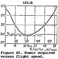
To construct the power required and available curves we use the curve of Figure 62. We find the power available at rated and takeoff engine rpm from the formulas

N.. = N I,
avail e

Characteristic Helicopter Horizontal Flight Spe

Characteristic Helicopter Horizontal Flight Spe

We use these values to plot a curve (Figure 63a), which permits deter­mining the following characteristic horizontal helicopter flight speeds:

Characteristic Helicopter Horizontal Flight Spe

Characteristic Helicopter Horizontal Flight Spe

Figure 63. Power required and available as a function

of

helicopter we

ight

and

flight

1)

N

a

for

H = 0,

n =

2200

rpm;

2)

N

a

for

H = 0,

n –

2050

rpm;

3)

Nh

for

H = 0,

G =

2200

kgf;

4)

Nh

for

H = 0,

G =

2300

kgf.

1. The maximal speed, which corresponds to the point of intersection of the power required and available curves. When using rated engine power, the maximal horizontal flight speed at sea level will be about 165 km/hr; when using takeoff power, this speed will be 208 km/hr.

2. The optimal velocity at which the longest flight range is obtained.

This speed corresponds to the point of contact of a tangent drawn from the coordinate origin to the power required curve (for the Mi-1, V t = 90-95 km/hr),

3. The economical speed, i. e., the speed corresponding to minimal power required (for the Mi-1, Vgc = 80 km/hr).

4. The minimal speed. When using rated power at a flight weight of /94

2200 kgf, the helicopter cannot hover at sea level. It can only perform hori­zontal flight with a speed of about 20 km/hr. However, heavy vibration develops at low speed; therefore, the constructor has established speed limi­tations: minimal permissible is 40 km/hr, maximal permissible is 170 km/hr.

5. The horizontal flight speed range, i. e., the speeds at which horizon­tal flight is possible. When using rated power the speed range is

ду = V – V. = 165 – 20 = 145 km/hr.

rat max mxn

When using more than rated power, the total speed range is V t = 170 – 0 = = 170 km/hr.

6. The excess power, i. e., the difference between the power available and required for horizontal flight at a given speed. Each speed is associated with a given excess power AN = ^ – N^. The maximal excess power will

occur for flight at the economical speed.

Landing

Landing is transitional flight from a height of 25 – 50 m with reduction of the velocity and subsequent touchdown. Helicopter landing may be performed in helicopter style, in airplane style, in the autorotative regime, from a glide along an inclined trajectory, and with flare-out.

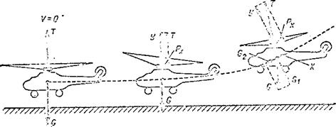
The helicopter-style landing is the primary technique for landing with the engine operating. It includes the following stages (Figure 91):

(1) glide with reduction of the speed along the trajectory and vertical rate of descent;

(2) hover at a height 2 – 3 m above the landing area;

(3) vertical descent;

(4) touchdown.

During the landing approach the helicopter performs steady-state descent along an inclined trajectory with the engine operating. At a height of 40 – 50 m reduction of the speed along the trajectory is initiated while maintain­ing a constant descent angle. In this stage the motion of the helicopter is governed by the following conditions:

О > O’

77/’//У/У//77Ї7УУ’ "/7/ / 77^/~ґ7?~77^7/УУ777У/у///’//////////У/У///,

і О*

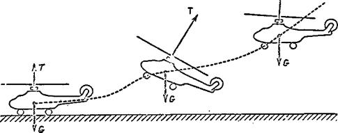
Figure 90. Takeoff on air cushion.

Landing

Figure 91. Helicopter-type landing.

Y = G^ = G cos 0 (constant descent angle);

P + X > G_ (reduction of the speed); x par 2

T = S (absence of lateral displacement); t. r s

M = M and EM = 0 (constant direction of flight, i. e., absence of r t. r eg

rotation about the helicopter’s primary axes).

Deceleration of the helicopter is achieved by tilting the main rotor
thrust force vector aft and increasing the thrust component P. Upon reaching

a speed of 50 – 60 km/hr, the vertical rate of descent is reduced by increasing main rotor pitch and its thrust force. The helicopter deviates from the descent path angle and travels parallel to the surface of the ground at a height of 2 – 3 m. During this inertial motion the speed decreases to zero and the helicopter hovers above the landing area, orienting itself relative to the center of the area. If the landing approach was not made directly into the wind, the helicopter is turned about the vertical axis to take up a heading into the wind. Then a vertical descent is made at a low rate in order to avoid rough contact of the wheels with the ground.

The airplane-type landing is made under the same conditions as the take­off of the same type. It includes the following stages (Figure 92): glide

from a height of 15 – 30 m, flare, holdoff, touchdown, and rollout. During the descent altitude is lost, but a constant speed and descent angle are maintained. The descent is made with the engine operating. The flare is initiated at a height of 7 – 10 m by increasing the thrust and lift forces.

Landing

touchdown and rollout. transition1 flare’ glide

Figure 92. Airplane-type landing.

The flare is terminated at a height of 1 – 0.5 m and the horizontal component of the velocity diminishes at this point, since the weight force component decreases to zero. After the flare the helicopter still has a relatively high speed, which is then reduced during the holdoff period. The

touchdown is made on the main gear wheels at a speed of 30 – 40 km/hr. In this procedure care must be taken that the tail does not get too low, since damage to the tail skid and the tail rotor can occur. The touchdown is followed by rollout, during which the main rotor thrust is decreased. An airfield or a smooth area with firm soil is necessary for the airplane-type landing.

Landing under special conditions. If the landing area is surrounded by obstacles, a helicopter-type landing is made without utilization of the "air cushion." Hovering is performed into the wind at a height of 5 – 10 m above the obstacles to align the helicopter with the center of the area. Then a vertical descent is made at a rate of descent of no more than 2 m/sec in order to avoid the vortex ring state. During this descent the vertical velocity of the helicopter is reduced to 0.2 – 0.3 m/sec at the moment of touchdown. Therefore, this type of landing can only he made if there is sufficient power margin available for hovering outside the "air cushion" influence zone. This type of landing is used only in case of extreme urgency, since a safe landing is not guaranteed in case of engine failure at a height of more than 10 m (in the danger zone).

Landing in the main rotor autorotation regime with glide along an inclined trajectory. We have established above that in case of engine failure flight in the main rotor autorotation regime should be made along an inclined trajectory rather than vertically.

Landing from a glide along an inclined trajectory is similar to the landing of an airplane and requires a smooth area with solid ground. It consists of the following stages (Figure 93):

(1) glide at constant angle and constant speed;

(2) deceleration (reduction of glide angle and vertical rate of descent through use of the kinetic energy of the helicopter and the main rotor);

Figure 93. Autorotative landing.


Landing

(3) touchdown;

(4) rollout and reduction of main rotor pitch.

The advantage of this landing is that the helicopter has considerably less /147 vertical velocity and better controllability. In addition, during flight along the inclined trajectory the helicopter has considerable kinetic energy, which is used to reduce the vertical velocity prior to touchdown. Therefore, the landing is safer and simpler when the helicopter approaches in a glide along an inclined path. This type of landing utilizes the kinetic energy of the entire helicopter, as well as the kinetic energy of the main rotor.

During the glide a constant descent angle is assured by the condition

У — Gt = G CO? 0,

and constant velocity is assured by the condition (see Figure 92)

Подпись: G2 =X + P. par x‘

The gliding speed is close to the economical speed for level flight, but it changes as a function of the wind velocity and direction. When gliding і nto the wind the helicopter speed should be higher, the higher the wind velocity.

The height for initiation of the deceleration or flare is different on different helicopters: the higher the disk loading, the higher this height.

For example, this height for the Mi-1 is 15 – 20 m; for the Mi-4 it is 25 – 20 m. Deceleration is obtained by tilting the main rotor coning axis aft. This leads to increase of the main rotor angle of attack and increase of the angle of attack of each blade element, which then leads to increase of the main rotor thrust force and its rpm. Therefore, both the glide angle and the velocity along the trajectory decrease. After the coning axis is deflected aft, the main rotor collective pitch must be increased to the maximal value. This leads to further increase of the thrust force and reduc­tion of the vertical rate of descent. The helicopter will travel for some time parallel to the ground surface, similar to the motion of an airplane during transition. The height at the end of this motion decreases to 0.5 – 0.3 m and the helicopter touches down with vertical velocity close to zero.

During the flare and transition the helicopter nose is high. Touchdown cannot be made in this attitude because of danger of damage to the tail rotor. Therefore, prior to touchdown the helicopter’s nose is lowered by deflecting the cyclic control stick forward. The increase of main rotor pitch leads not only to increase of the thrust force, but also to increase of the resis­tance to rotation; the rotor rpm decreases and the coning angle increases (blades flap up). If the rotor pitch is not reduced after touchdown, the rotor blade may descend abruptly and strike the tail boom.

Landing in the autorotative regime with vertical descent. If the landing /148 is made on a small area which is surrounded by obstacles, the landing must be made from a vertical descent. It was established earlier that the vertical rate of descent during flight in the autorotative regime along a vertical

trajectory is found from the formula = 3.6 tF and amounts to 14 – 20 m/sec.

Touchdown at such a velocity leads to damage to the helicopter and does not guarantee safety of the crew. Therefore, the velocity is reduced prior to touchdown by utilizing the kinetic energy of the main rotor. Such a landing is called a landing with flare-out. The essence of the operation is as follows.

At a height of 20 – 25 m the main rotor pitch is increased to the maximal

value, and the main rotor rpm should be as large as possible in order to

impart maximal kinetic energy to the main rotor (the kinetic energy is propor – 2

tional to to ). As the pitch is increased there is a marked increase of main rotor thrust flare-out, which leads to reduction of the vertical rate of descent to 3 – 5 m/sec. Such a velocity can be abosrbed completely by the gear shock absorbers, and a safe landing can be made.

The landing is easier when there is a wind. In this case the helicopter is turned into the wind and transitioned into the inclined glide regime (slope 45°). The effect of the wind is to carry the helicopter aft, and its trajectory relative to the ground will be nearly vertical. The helicopter controllability is better in this type of glide, and the thrust force is increased somewhat as a result of forward flight.

A vertical landing in the autorotation regime requires considerable skill and coolness on the part of the pilot. The following errors are possible in this type of landing:

(1) early flare-out (reduction of vertical velocity at a high altitude);

(2) late flare-out, as a result of which the vertical velocity is not reduced and hard contact with the ground may result.

It is clear from this discussion that the velocity is not entirely arrested in landing from a vertical descent. Even when the flare-out is

performed correctly, the final velocity may be quite large — 3-5 m/sec or more. This is explained by the fact that the helicopter, which has a rate of descent prior to flare-out of 15 – 20 m/sec, has considerable kinetic / C7V?

energy! s= —2^eSj • e4uiva3-ent kinetic energy of the main rotor must be

expended to arrest the vertical velocity completely. But the main rotor

kinetic energy is not entirely utilized for braking the helicopter. A large

part of the rotor energy is expended in overcoming the profile and induced

drags, on friction in the transmission, and on the blade end losses. Only

one fifth or sixth of the total kinetic energy of the main rotor is used for

deceleration. This means that the main rotor must have 5-7 times the kinetic /149

energy of the helicopter in order to decelerate the helicopter completely.

In reality the main rotor kinetic energy is about three times the helicopter kinetic energy.

Landing

Therefore, the vertical velocity cannot be arrested completely, but it must be reduced as much as possible, and to this end the main rotor rotational energy is increased; this energy is proportional to the blade mass and the square of the angular velocity of revolution

where is the rotational kinetic energy;

j is the main rotor moment of inertia;

Подпись: j9.b’L p~

JV •

Substituting the value of the rotational moment of inertia into the formula, we obtain

We see from the formula that heavier blades are required for safe landing in the autorotation regime.

CHAPTER XI

Main Rotor Coning Axis Tilt

With variation of the flapping angles the plane of rotation and the coning axis deflect backward and to the side in the direction of the advancing blade through the angle т (Figure 38a). As a result of the tilt of the coning axis backward by the angle a^, there is an increase of the blade flap­ping angle to 8 = + a^ at the 180° azimuth and a reduction to 8 = a^ – a^

at the 0° azimuth (Figure 38b). Tilting of the cone axis to the side by the angle b^ leads to change of the flapping angles: at the azimuth 90° 8 = ад – b^; at the azimuth 270° 8 = a. Q + b^ (Figure 38c).

Main Rotor Coning Axis Tilt

Figure 38. Blade flapping motions and tilt of main rotor cone axis. 1 – cone for p = 0; 2 – cone for у > 0.

Tilting of the cone axis backward by the angle a^ leads to deflection /55

through the same angle of the thrust vector and the formation of the longitud­inal thrust component H (Figure 39a). This force is the projection of the main rotor thrust on the hub rotation plane. Since it is directed aft, it is a drag force and is analogous to the induced drag of an airplane wing. The

Main Rotor Coning Axis Tilt

Figure 39. Main rotor thrust force components.

larger the flapping motions, the larger the backward tilt of the cone axis and the larger the longitudinal force H resisting helicopter forward motion. Consequently, the flapping motions in the forward flight regime must be restricted.

If the deflected thrust T is projected on the hub axis, we obtain the force required for helicopter flight

Ty =.T cos au

In view of the smallness of the angle a^(2 – 3°) we can take a^ « 1. /56

Then T и T.

У

The sideward tilt of the cone axis (Figure 39b) leads to the appearance of the side force Sg, which is the projection of the main rotor thrust on the hub rotation plane

S = T sin b.• s 1

Since this force is directed to the left, this direction is unfavorable for single-rotor helicopters. Therefore, the blade flapping motions must be restricted in order to alter the sideward tilt of the cone angle from the

left to the right. Moreover, restriction of the flapping motions is also necessary to reduce main rotor vibrations.