Category Helicopter Test and Evaluation

5.3.3 Manoeuvring at reduced load factor

For rotors where rotation of the thrust vector is the only source of a control moment (such as teetering rotors) the ability to control the helicopter will disappear if the load factor should ever reach zero. Hingeless rotors or those with some effective hinge offset will maintain more control power at low rotor thrust, but it might be noticeable that more cyclic control is required to return to level flight from a 0.5g push-over than from a 1.5g pull-up. Not only is control power reduced at low rotor thrust, but it can set up a potentially dangerous condition leading to ‘mast bumping’ on teetering rotor helicopters or ‘droop stop pounding’ on those helicopters with articulated rotors of low hinge offset. In either case, at a low load factor the tip path plane will respond normally to cyclic inputs, but the low rotor thrust will have little effect on fuselage attitude. The ultimate effect of this critical situation is that the rotor may flap outside design limits, leading to blade/fuselage contact or rotor separation due to mast shearing. A further degradation of handling qualities at low rotor thrust results from the reduction in the rotor’s contribution to rate damping (in both pitch and roll) since the damping effect of thrust tilt is reduced.

5.4 DOCUMENTING DYNAMIC STABILITY CHARACTERISTICS

5.4.1 The longitudinal long-term mode

All dynamic stability testing, but especially long-term response testing, demands that the initial trim flight condition be set up as accurately as possible. If this is not achieved then any control offset will bias the response and may cause, for example, a lightly damped oscillatory response to diverge aperiodically. If a very accurate engineer­ing assessment of long-term response is required, then the tests are conducted in conditions of zero turbulence. In addition to quantitative tests, qualitative testing is conducted during role manoeuvres and comprises observing the pilot compensation necessary to suppress any undesirable dynamic effects such as a lightly damped long­term mode. Often it is these qualitative tests that are the most important part of the test programme as they show how the aircraft’s stability characteristics will affect the operational pilot when conducting the role.

To avoid damaging the aircraft during the large excursions from straight and level flight that can occur when documenting an aggressively unstable long-term mode it is often necessary for the aircraft to be instrumented with stress parameters monitored by telemetry. Practice recoveries from unusual attitudes followed by an incremental approach with some form of in-flight prediction of the severity of the next response, similar to that described in the section on lever delay testing, should prevent any exceedence of limits.

Effect of changes in collective pitch

The concept of using turning flight as a method of assessing manoeuvre stability can be extended to encompass the more role-relatable case of a level turn at constant speed. As with the descending turn, since the load factor will be related to the bank angle the severity of the manoeuvre can be incrementally increased. The complication introduced by level turns is that in order to maintain height collective pitch will be required and the pitch change with power effect will require cyclic pitch to compensate. Assuming that an increase in collective pitch causes a nose-up pitching moment it is clear that a level turn will require less aft cyclic than a descending turn at the same load factor (angle of bank). Therefore, to the pilot, the helicopter will appear to be less manoeuvre stable. In order to make the distinction between these two cases the following terminology is used: collective fixed manoeuvre stability (assessed either during pull-ups/push-overs or during descending turns at constant speed and fixed collective) and apparent manoeuvre stability (assessed during level turns at constant speed).

5.3.2.1 Test techniques

Although apparent static stability tests are role relatable in that most steep turns are conducted in level flight (albeit not necessarily at constant IAS), they are of limited use in determining the true characteristics of the aircraft since, as stated above, the increased collective necessary to sustain level flight at high angles of bank is usually destabilizing. Additionally the Ministry of Defence Standard 00-970 [5.1] requires manoeuvre stability to be evaluated in a turn initiated from steady straight and level flight conditions. Consequently both forms of stability testing are conducted.

Descending turns at fixed collective, or wind-up turns, are commenced by first establishing a trim condition in level unaccelerated, ball-centred flight at the datum altitude. The aircraft is then climbed a suitable increment above datum altitude, without re-trimming, and the trim control positions (collective and longitudinal) are re-established. A constant airspeed, ball-centred, fixed-collective descending turn is then entered aiming to be on condition in stable flight at the desired bank angle, and therefore load factor, as the datum altitude is passed. Data is normally recorded continuously in an altitude band +1000 ft from datum, the most stable 10 seconds or so being selected for analysis after the flight. Data typically includes airspeed, load factor, longitudinal cyclic stick position and fuel state. The test is then repeated at incrementally increasing bank angle until a limiting condition (angle of bank or load factor) is reached. At small bank angles it is often possible to complete several test points within the test altitude band before having to climb back up.

Manoeuvre stability during symmetric manoeuvres can be evaluated by studying the normal acceleration time history following a pull-up or push-over. Since a key parameter in manoeuvre stability testing is airspeed it should be maintained essentially constant. This exposes a complication with symmetric manoeuvres since the change in flight path angle results in a variation in the ‘X’ component of gravity causing a change in airspeed and an attitude-related change in normal acceleration as measured in the ‘Z’ axis of the aircraft. The corollary of these two effects is that data must be taken during the short period when forward velocity is essentially equal to the datum airspeed and when the aircraft is in the level pitch attitude. The type of manoeuvre necessary to comply with these constraints is difficult to fly accurately. The Ministry of Defence Standard 00-970 [5.1] attempts to get around these problems by requiring only that the peak increment in normal acceleration should be ‘substantially propor­tional to the magnitude of the control input’ and that it should ‘increase progressively with increasing initial airspeed ’, the implication being that testing can be achieved by incremental step inputs from trimmed, level, unaccelerated flight. Nevertheless, in order to allow enough time to develop peak load factor in an agile aircraft, it is necessary to commence the manoeuvre from a nose-down attitude so that the recovery can be made before an excessive nose-up condition develops. A control fixture can be used to provide some means of incrementally increasing the severity of the manoeuvre. Push-overs are always approached with the utmost caution in helicopters with teetering rotors or with articulated rotors featuring low hinge offset. The technique is the reverse of that for the pull-ups: the aircraft is accelerated/descended from the trim condition, pulled up to a nose-high attitude and then bunted using the appropriate control input as it decelerates towards the trim speed.

Flight test methods and results

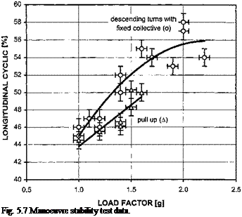
The differences in the pitch rate generated during the two tests will lead to differences in the amount of aft stick required. The main reason for the difference is the greater pitch damping moment (Mq) generated in the turn requires more aft cyclic to compensate. Since there will usually be a linear relationship between longitudinal cyclic stick position and cyclic pitch (Bl) these equations can be used to explain the difference in test results assuming all other factors are equal, see Fig. 5.7.

Подпись: Fig. 5.7 Manoeuvre stability test data.

The figure shows that as far as the pilot is concerned the helicopter will appear more manoeuvre stable in a descending turn than during a pull-up. Note, however, that since MBl appears in both equations the actual amount of manoeuvre stability (size of Mw) cannot be quantified since the size of the control deflection is dependent on the control power.

MANOEUVRE STABILITY TESTING

The manoeuvre stability of a helicopter will manifest itself to the pilot as the amount of aft stick required to maintain an elevated load factor. The pilot can achieve such a load factor either in a pull-up manoeuvre or during turning flight. Therefore manoeuvre stability can be assessed in either situation. (Push-overs can be used to assess stability at reduced load factor.) The pros and cons of each method are:

(1) Pull-ups. The pull-up manoeuvre is easily role-relatable and does not give false’ data since the radius of the circular flight path is in line with the normal axis of the helicopter. The test technique which requires achievement of the elevated load factor in level flight, at zero pitch attitude, on speed and with the collective fixed at PFLF is, however, difficult to fly accurately and repeatably. It is also not possible to assess manoeuvre instability using PUPOs as it will be impossible to establish the correct balance of flight parameters.

(2) Turning flight. Descending turns, at constant speed with fixed collective (at PFLF), are, perhaps, less easy to role-relate. This manoeuvre is, however, easier to fly accurately and provides a method of incrementally increasing the load factor by simply increasing the angle of bank. The data obtained will be ‘false’ since for a given load factor a greater pitch rate will be required than for a pull – up because the centrifugal acceleration is not aligned with the normal axis of the helicopter (except at 90° of bank). Despite the increased workload it is possible to temporarily stabilize a manoeuvre unstable aircraft during quantita­tive data gathering.

5.3.1 Theoretical treatment of test methods

5.3.1.1 Symmetrical pull-ups

During pull-up testing, as described earlier, the pilot endeavours to achieve the desired load factor with the aircraft at zero pitch attitude, wings level, on speed and with no
yaw rate developing. The tests are conducted with fixed collective and it is also assumed that a steady pitch rate is achieved. Therefore:

и = и = w = p = p = r = q = 0e = 80c = 0

Thus the linearized form of the longitudinal equations of motion reduce to:

– mqUe = w. Zw + q. Zq + SB,. ZBi

0 = w. Mw + q. Mq + SB,. MBi

Applying the concept of circular motion to the pull-up manoeuvre yields:

g

qPun-uP = и(n -1)

Ue

Substituting and solving simultaneously:

SB, = g ГMqZw – mUeMw – ZqMw (n – 1) Ue ZB, Mw – MB, Zw

Assuming that Zq = 0:

dB, = g MqZw – mUeMw dn = Ue ZB, Mw – MB, Zw

5.3.1.2 Steady turns

Consider a helicopter performing a steady turn with fixed collective. Assuming that the flight path angle and bank angle are small then it is accurate to assume that the thrust vector acts parallel to the rotor shaft. For equilibrium:

mg = Tcos ф CF = T sin ф CF = mRturn m2

Now:

T Vmg2 + CF2 Г Zcf 2 1

ntur n = = = 1 + ( I = Г

mg mg ^ mg I cos ф

The linear and angular velocities can be related by:

CF = mRturn m2 = mVm

If the flight path angle is small and w, the vertical velocity, is small then V = Ue. Thus:

nt2urn = 1 + j and m = g Vntum – 1

Noting that the pitch rate, q, is related to the rate of turn (in a vertical bank they would be equal) by qturn = m sin ф, gives:

Подпись: qtur ng (nt2urn – 1)

Un

Подпись: dBj dq Подпись: Mq. Zw — mUeMw ZBl . Mw — MBl. Zw Подпись: and Подпись: dBl _ dBl dq dn dq 'dn

It is evident from the above equation that the pitch rate required in a turn is greater than a pull-up for the same load factor. Since:

n2 + 1

Подпись: dBl _ g MqZw — mUe Mw dn _ Ue ZBl Mw — MBl Zw
Подпись: n
Подпись: 2

then:

Turns on one control

As discussed above the standard test for lateral and directional static stability is the steady heading sideslip (SHSS). The problem with this test technique is that it only indicates cockpit stability, that is how the stability appears to the pilot. A technique that may be of use in determining the relationship between stability and control power is that of turns on one control or ‘TO1C’. Although a co-ordinated turn normally involves both cyclic and pedal movements and possibly collective control, consider what happens if an attempt is made to turn the helicopter using only one control, cyclic stick or pedals, while the other is fixed.

Подпись: tr Turns on one control

From a condition of steady, trimmed level flight, consider the effects of initiating a turn to starboard using yaw pedals only. Firstly, as right pedal is pushed forward the helicopter will yaw to the right and sideslip to the left. The sideslip will cause the rotor disk to flap away from the relative airflow and this will produce a rolling moment to starboard. The subsequent bank to starboard will reduce the sideslip to the left and eventually cause a sideslip to the right. Finally, the helicopter will settle into a steady turn with the yaw pedal deflection adjusted as necessary to maintain the roll attitude of the aircraft. It will then normally have adopted an attitude in which it is yawing to starboard, sideslipping to starboard, banked to starboard. The amount of sideslip required to generate the roll response will indicate the strength of Lv since the test has not involved any contribution from LM. This, of course, assumes that the rolling moment due to pedal L0tr is negligible. Consideration of the stabilized turn leads to:

Assume a starboard turn (r positive) with starboard sideslip (v positive). The turn is opposed by the yaw damping (Nr being negative) and assisted by the directional stability
(Nv being positive). Thus, Nr. r is negative and Nv. v is positive so the sign of the term (Nr. r + Nv. v) depends on the relative magnitudes of the two terms. As N9tr is negative by defintion, if (Nr. r + Nv. v) is negative then 9tr will be positive and vice versa. The pedal deflection required can therefore be summarized as follows:

• The yaw pedals are deflected to yaw the helicopter into the turn (right pedal forward, 9tr is negative), then Nr. r > Nv. v and the yaw damping term is dominant.

• The yaw pedals are deflected to yaw the helicopter out of the turn (left pedal forward, 9tr is positive), then Nr. r < Nv. v and the directional stability term is dominant.

• No pedal movement from the trim position is necessary to maintain the turn (9tr is zero), then Nr. r = Nv. v and neither term is dominant.

Thus it is possible during the stabilized portion of a turn on one control-pedal (TO1C – P) to determine the relative magnitudes of the directional stability and the yaw damping. Equally the strength of the Lv effect can be gauged by the readiness with which the helicopter responds in roll to the sideslip generated by a TO1C-P. Assuming there is little or no contribution from L9a, strong lateral stability will be present if the helicopter rolls smartly to the right following the application of right pedal and the onset of left sideslip. Pedal-only turns are generally more difficult to perform than turns on cyclic alone (see later discussion) as some sideslip must be generated before the aircraft responds, as there will be a lag between yaw pedal application and the helicopter rolling into a turn. Consequently the input is usually in the form of a steady ramp with the rate of application varied to establish whether this has an effect on the subsequent response of the aircraft. Care must be exercised, as it is relatively easy to exceed sideslip limits during this test. Longitudinal cyclic is used as necessary to maintain the airspeed.

Now consider the effects of initiating a turn to starboard using lateral cyclic only. Firstly, as right cyclic is applied the helicopter will roll to the right and commence sideslipping to the right as the aircraft descends. The sideslip will cause the tail rotor and fin to generate a yaw moment starboard. Eventually, the helicopter will settle into a steady turn with the lateral cyclic deflection adjusted as necessary to maintain the roll attitude of the aircraft. The amount of sideslip required to generate the yaw response will indicate the strength of Nv since the test has not involved any contribution from N9a. This, of course, assumes that the yawing moment due to lateral cyclic NAl is negligible. Consideration of the stabilized turn yields:

Ai = – L~(Lr. r + Lv. v)

LAl

In a turn to starboard (r positive) with starboard sideslip (v positive), Lr. r will be positive (act to starboard) whilst Lv. v will be negative (act to port). As LA is negative, by definition Al will be positive if (L. r>Lv. v) and negative if (Lr. r < Lv. v). The control deflection can thus be summarized as: [10]

• Once established in the turn no cyclic movement from the position required for trim is necessary therefore neither term dominates as Lr. r = Lv. v.

With the aircraft established in a steady constant bank angle turn inspection of a sideslip gauge, skid-ball or suitably mounted string will confirm the strength of Nv. Weak directional stability will be evident if large values of sideslip are observed. Alterna­tively, strong directional stability will be evident if little sideslip is recorded.

Turns on one control-cyclic (TO1C-C) testing begins by stabilizing the helicopter at the required balanced flight condition and recording the trimmed control positions, aircraft heading, sideslip and bank angle. The rate of application and the magnitude of the lateral cyclic displacement is chosen to achieve a bank angle which is related to the requirements of the role, although the bank angle chosen should be approached incrementally (20° is a good initial condition). At the desired bank angle longitudinal cyclic is used as necessary to maintain constant IAS. The cyclic is then returned to the initial trim condition before the test is repeated in the opposite direction.

Lateral and directional static stability

5.2.2.1 Steady heading sideslips

The control deflections required to maintain an unaugmented helicopter in a steady sideslip are related to its lateral and directional static stabilities. In a steady sideslip the rates of roll and yaw will be zero, therefore the rolling and yawing aerodynamic moments must have been balanced by control deflections generating control moments. The linearized form of the lateral/directional equations of motion for a helicopter, with the centre of gravity situated at the body axes origin, can be written as follows:

m[rUe + v – pWe ] = Yv. v + Yp . p + Yr. r + mgф cos 6e + YA, . A, + Y0tr. 6tr

Ixxp – Ixzr = Lv. v + Lp. p + Lr. r + LM. A, + L0tr. 6tr

Izzr – Ixzp = Nv. v + Np. p + Nr. r + NA, . A, + N0tr. 6tr

Now when performing a SHSS the pilot endeavours to achieve the off-trim condition by co-ordinated movement of both the lateral cyclic and the yaw pedals without developing any sustained pitch, roll or yaw rate. Once ‘on-condition’ the lateral velocity will be constant, indicated by a fixed sideslip angle. So:

v = p = Г = p = r = 0

Thus the equations of motion reduce to:

0 = Yv. v + mgф cos 0e + YA,. A, + Y. tr. 0tr

0 = Lv. v + [8]a,. Ai + L0tr. 0tr

0 = Nv. v + Na, . A, + N0tr. 0tr

If it is assumed that the roll attitude remains small, such that ф в 0, then:

0 = Yv. v + YA,. A, + Y0tr. 0tr

0 = Lv. v + LA, . A, + L0tr. 0tr

0 = Nv. v + Na, . A, + N0tr. 0tr which leads to:

0 = v(Yv. L0tr – Y0tr. Lv) + A,(YA,. L0tr – Y0tr. LA,)

A, = (Yv. L0tr – Y0tr. Lv) v (Y0tr. lm – ym . L0tr)

If the rolling moment due to tail rotor collective (pedal) is negligible, such that L0tr = 0, then:

A = -_L_ v La,

also:

0 = v(Yv. NAl – YAl. Nv) + 0tr (F0tr. NAl – YAl. N0„)

0tr (Yv. NAl – YAi. Nv)

v = (YAl. N0tr – Y0tr. NAl)

If the yawing moment due to lateral cyclic is negligible, such that NAl = 0, then:

0Г = – N

v N0tr

For positive lateral static stability, the slope of the control deflection versus sideslip graph will be negative. That is, in order to increase sideslip to starboard the pilot must apply an increased right lateral cyclic stick deflection. For positive directional static stability, the slope of the pedal deflection versus sideslip graph will be positive. That is, in order to increase sideslip to starboard the pilot must apply increased left pedal. Note that in each case the magnitude of the control deflection required to maintain a given sideslip angle depends, on the degree of stability and the amount of control power. Useful techniques to determine the relationship between stability and control power are turns on one control (TO1C) which are described later.

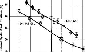
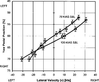
As PEs are often present in sideslipping flight the test technique consists of stabilizing in a steady heading sideslip at constant EAS, recording roll attitude, lateral cyclic and yaw pedal positions. It should be noted that steady heading sideslip (SHSS) tests will only indicate the amount of control displacement required to counter the rolling and yawing moments generated by the sideslip. The amount of control displacement should increase as lateral velocity increases and for stability should be in the same direction as the sideslip for lateral cyclic and in opposition for the yaw pedals. Whether, for example, a small control displacement is due to weak stability or high control power must be determined by some other test technique such as turns on one control, which are described later. Figures 5.5 and 5.6 illustrate the presentation of typical results. From these plots it can be seen that at each speed the control movement is in the correct sense and that increasing control deflection is required for increasing lateral velocity.

Tests are normally made in level flight at the minimum power speed, VNE – 20 kts and one intermediate speed. In climbing and autorotative flight the speed will normally be the recommended climbing speed and the speed for minimum rate of descent in autorotation respectively. If no sideslip angle indicator is fitted an approximation of sideslip can be obtained by employing one of the methods described below: 1 [9]

зо

LEFT

image115

RIGHT

60 ————————————————————————————————

-40 -30 -20 -10 0 10 20 30 40

LEFT Lateral Velocity (v) [kts] RIGHT

Fig. 5.5 SHSS test data – lateral static stability.

image116

Fig. 5.6 SHSS test data – directional static stability.

Note the actual heading change when established in a steady-state condition and this approximates to the sideslip angle.

An approximate ‘calibration’ of slip-ball displacement to sideslip angle can also be obtained during either of the above techniques. Also, if a suitable line feature is
selected and there is no wind (or very light wind down the line feature) it may be possible to estimate inherent sideslip by noting the line feature heading and then comparing this to the heading required to track down the line feature with wings level and ball centred. The difference between the line feature heading and the heading required to track the line feature will equate to the inherent sideslip value for the test airspeed.

Before starting, the ASI PECs with sideslip are obtained for the test speeds. This is particularly important at high IAS to avoid exceeding VNE. Steady sideslips are flown at constant EAS to eliminate inconsistencies due to pressure errors at high angles of sideslip. If ASI PECs with sideslip are not available, it should be possible to obtain satisfactory steady sideslip results by using the following method:

(1) Stabilize the aircraft wings level with inherent sideslip (ball centred) at the IAS which gives the EAS for the test condition.

(2) Smoothly but rapidly yaw the aircraft to the required sideslip angle controlling the bank with lateral cyclic to maintain a SHSS, and note the new IAS immediately.

(3) Maintain this IAS and record the test parameters.

(4) Yaw the aircraft smartly back to wings level and the inherent sideslip value (ball centred) and note that the IAS returns to the original value.

Trimmed flight control positions tests

Determining the theoretical variation of longitudinal cyclic pitch, and pitch attitude, with trimmed airspeed is more difficult. The control deflection required and the aircraft attitude is dictated by the requirement to achieve equilibrium of both forces and moments whilst maintaining level flight. Basically equations arising from considering equilibrium of X-force, Z-force and M-moment are obtained. At each trim condition these equations are solved simultaneously to give values for longitudinal flapping, relative to the shaft (als), pitch attitude (0) and thrust. These are then used to determine the longitudinal cyclic pitch (Bl) and cyclic stick position required. On a conventional helicopter the M0c effect on cyclic position will be the same as those seen during steady climbs and descents at the same collective pitch and off-trim airspeed. A forward longitudinal control displacement or force should be required in order to initiate and maintain an increased forward airspeed [5.1]. Pitch attitude variation with airspeed will typically be a compromise between maintaining a near level attitude for crew comfort and profile drag considerations, whilst achieving pitch attitudes relatable to airspeeds for instrument flight.

5.2.1.2 Practical considerations

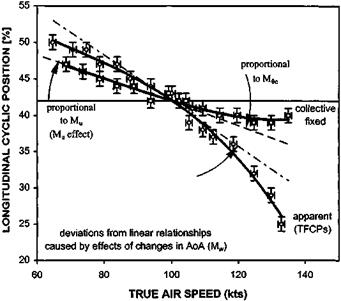
Provided only small speed changes are made during collective fixed static stability (CFSS) testing, and the same range of airspeeds are evaluated during a TFCP test, the effect of changes in collective pitch or power (M0 ) can be evaluated by direct compari­son. Consider Fig. 5.4 which shows the typical case of a helicopter with a nose-up trim change with increased power (collective). Above minimum power speed the pilot must increase collective pitch to generate sufficient thrust to maintain level flight at higher speeds. He must now apply extra forward cyclic, to counter the nose-up cross-coupling effect over and above that required to overcome the basic pitch-up tendency with increased speed (flap-back effect). Static stability test results would, therefore, show ‘increased stability’ when TFCP results were compared with data obtained from a collective fixed test. Note that the speed stability, or Mu effect, can also be clearly seen by comparing the collective fixed test data with a horizontal line from the trim point (Mu = 0). The non-linear nature of the M0c effect can be explained with reference to a typical power curve where the power decrement required to maintain a lower speed in level flight reduces as the minimum power speed is approached.

CFSS tests are normally accomplished by establishing a trim condition (airspeed/

image114

Fig. 5.4 Longitudinal static stability test data.

power combination) with zero control forces. Then without changing the collective position, trim setting or rotor speed, the helicopter is stabilized at incremental airspeeds both faster and slower than the trim airspeed using cyclic only. Directional control inputs are made to maintain ball centred or zero sideslip flight. An airspeed range either side of trim is assessed using 2 knot then 5 knot increments. Ideally the helicopter is kept within 1000 feet of the specified test altitude. Airspeeds faster or slower than trim are flown alternately to achieve this. Excursions from the test altitude band can be corrected using the collective control. To achieve this the collective trim position or power/torque for level flight at the datum speed is noted. Collective pitch is then used as required to regain the desired altitude and, without re-trimming the cyclic, is adjusted back to its initial position before the test is continued.

Although, as discussed, the collective to pitch coupling can be discerned by comparison between TFCP testing in level flight and collective fixed data, the coupling can also be evaluated by performing trimmed climbs and descents at constant airspeed. As well as highlighting any problems with excessive collective-to-pitch cross-coupling these tests will identify the possibility of an encroachment of control margins. Discontinuities in the collective position versus longitudinal control position data may suggest handling problems caused by, for example, the stalling of a down-loaded tailplane at high negative angles of attack which may occur at high ROC and low IAS. TFCPs are normally evaluated at a number of key role-relatable airspeeds such as climbing/endurance/autorotation speed, cruise speed and maximum level flight speed. Since M0c increases with airspeed it is normal to evaluate the lower speeds first.

In summary, during static (speed) stability tests the aim is to identify the Mu effect (collective fixed) and the M0c effect (TFCPs in climbs/descents and collective fixed versus TFCPs in level flight). If, however, during these tests the angle of attack changes markedly from its value at the trim point (level flight at the trim speed) it is possible that Mw effects will corrupt the results. Typical advice is therefore to only test modest deviations from trim ( + 15 kts for collective fixed static stability tests and +1000 fpm for TFCPs in climbs/descents).

U = w = p = q = p = q = r = Qc = 0 Thus the equations of motion reduce to

0 = Xu. и + Xw. w – mgQ cos Qe + XBl. Bl

0 = Zu. и + Zw. w – mgQ sin Qe + ZBl. Bl 0 = Mu. и + Mw. w + MBi. Bi

If it is assumed that the trimmed pitch attitude is small, such that cos Qe = 1 and sin Qe = Qe, then:

0 = Xu. и + Xw. w – mg Q + XBi. Bl 0 = Zu. и + Zw. w – mgQQe + ZBi. Bl 0 = Mu. и + Mw. w + MBi. Bi Thus:

w=–M – im„ .и+MBl. b ]

Mw

and assuming that the pitch attitude change is small:

0 = Zu. и + Zw. w – mgQQe + ZBl. Bl

Z

= Zu. и – M [Mu. и + MBi. Bl ] + ZBi. Bl

M w

0 = Mw Zu. и – Zw Mu. и – Zw MBl . Bi + Mw ZBl . Bi

= u[mw Zu – Zw Mu ] – Bi [Zw MBl – Mw ZBl ]

Bi = [Mw Zu – Zw Mu ]

U [ZW MBl – Mw ZBl ]

Since there is little change in vertical force with changes in longitudinal cyclic:

dB = Mw Zu – Zw Mu

du Zw MBi

this equation will only be valid if the pitch attitude required to hold the off-trim speed is not large when compared with the trim speed. Once again it should be appreciated that the presence of MBi (longitudinal cyclic control power) in the above equation means that the test cannot be used to evaluate the magnitude of the static stability (Mu) since the amount of stick deflection required is dependent on the control power. In addition it should be noted that the above equation contains a contribution from Mw. Only small excursions from the trim speed can, therefore, be tested since if large rates of descent or climb are experienced the results will be corrupted by Mw effects.

Trim system evaluation

The final part of the FCMC assessment is to measure the beeper trim system characteristics and then to determine their suitability for the intended role. For a ‘beeper’ trim system using a trim motor the two important aspects are firstly the trim rate and secondly any lag in the system. Measurement of the rate is made on the ground by operating the trim and obtaining the displacement against time from the data replay. If no instrumentation is available then displacement against time is measured using a stopwatch and tapes fitted to the control. To conduct the airborne evaluation flight tasks are selected which require accurate trimming and other tasks that require more rapid displacement of the control. Too rapid a trim rate is distracting and frustrating for the pilot conducting the precision task while too slow a rate requires the pilot to hold the trim force for too long after a larger displacement. When measuring trim lag the trim control is moved in one direction and then trimmed in the opposite direction to measure the time it takes for backlash in the system to be taken up and the flight control to be moved.

5.2 ASSESSING STATIC STABILITY

5.2.1 Longitudinal static stability

The static stability of a helicopter will manifest itself to the pilot as the amount of forward stick required to maintain an airspeed greater than trim. The pilot will also ‘expect’ to perceive some change in control position as he trims the helicopter through its speed range in level flight. There are, therefore, two different test techniques:

(1) Apparent static stability tests. The helicopter is trimmed, in level flight, at a series of airspeeds from minimum to maximum. The control position data obtained is often referred to as the ‘Trimmed Flight Control Positions’ (TFCPs). As suggested earlier TFCPs can also be assessed in steady climbing and descending flight.

(2) Collective fixed static stability tests. The helicopter is trimmed at an airspeed and the collective fixed at ‘Power For Level Flight (PFLF). The pilot then attempts to hold an off-trim speed, either greater or less, and accepts the ensuing climb or descent. The stick position data obtained in this test is directly related to the strength of the speed stability (Mu) provided the rate of climb or descent is not excessive and the control power is constant.

The difference in the results obtained from these tests will depend on the pitch response of the helicopter to changes in collective pitch. In addition to the control position data the variation of pitch attitude with airspeed is also noted. A large change in attitude with speed may be used by the pilot to compensate for poor cyclic stick position cues. If, on the other hand, the variation in attitude is very small the attitude hold function of an AFCS would not be very effective as an airspeed hold.

5.2.1.1 Collective fixed test results

The variation of longitudinal cyclic pitch (Bl) with airspeed from a trimmed condition is relatively easy to estimate theoretically. The linearized form of the longitudinal equations of motion for a helicopter, with the centre of gravity situated at the body axes origin, can be written as follows:

m[U – rVe + qWe] = Xu. и + Xw. w + Xq. q – mgQ cos 6e + XBi. Bl + X0c. 6c

m[w – qUe + qVe] = Zu. и + Zw. w + Zq. q – mgQ sin 6e + ZBi. Bl + Z0c. 6c

Iyyq – Ixz r – Ixzp = Mu. и + Mw. w + Mq. q + MBl. Bl + Mqc. Qc

When performing speed stability testing the pilot endeavours to achieve the desired off-trim speed with the aircraft wings level and with no pitch, roll or yaw rate evident. Therefore:

Freeplay

Freeplay will inevitably exist in any mechanical control system due to wear and backlash between the various components. Freeplay that exists between the flight controls and the blade pitch change linkage is termed total system freeplay while wear or backlash between the flight controls and the spring feel unit is termed trim system freeplay.

Measuring total system freeplay (for an irreversible system) is performed with rotors stopped and an observer stationed by the rotor head. The pilot makes control inputs in the axis under investigation and the observer confirms that a blade pitch change has taken place. The process is repeated using gradually smaller inputs until there is no resultant blade pitch change. Results can be confirmed with blades turning by observing the tip path plane and observing when there is no response to the control.

Total system freeplay is always undesirable as it will delay the aircraft response to inputs and therefore adversely affect handling qualities during tasks such as precision hovering which involve small, high-frequency control inputs.

Determining trim system freeplay is rather more straightforward and involves measuring the distance through which the control can be moved without needing to overcome a force. Although generally undesirable, some pilots like the opportunity that trim system freeplay affords to make small control adjustments without having to overcome B + F. Although it is different to a TCDB, a band of trim system freeplay does share the characteristic that control displacements within the band do not require operation of the trim system as there will be no force to hold off.

5.1.1 Assessing mass balance and control dynamics

The mass balance characteristics of the cyclic and collective are assessed to determine the tendency of the control to move due to the influence of gravity or other accelerations. Clearly this will usually only be a problem where there is no force feel system fitted or the force gradient is very shallow. The assessment is made initially with no control friction set to establish a base-line condition, and then repeated with ‘normal’ amounts of friction. Any manoeuvres which produce forces on the controls such as pull-ups/push-overs and steep turns can be employed. Poor mass balance characteristics can increase the pilot’s workload as it prevents the control being released for other than brief periods or requires any adjustable friction devices to be set to possibly undesirably high levels.

Identifying the control dynamics is an essential part of any FCMC assessment. This consists of evaluating the effect of control ‘raps’ and releases from an off-trim condition as well as assessing the effect of any biomechanical feedback and the mass balancing of controls. Although some limited testing can take place on the ground the majority of tests need to be conducted in-flight. Release-to-trim (RTT) tests of the cyclic and control raps of the cyclic and collective are approached with caution in case the control dynamics lead to a divergent aircraft response. For obvious reasons the tests are not conducted with the aircraft at the edges of the cleared flight envelope. The procedure involves two crew members; the handling pilot gives a countdown before each RTT or rap while the other crew member positions both hands near the control, ready to suppress any divergent response. A series of incremental RTTs or raps in each axis are made and the control dynamics recorded. For a well-damped response it is usually sufficient to record the number of overshoots but for less damped responses time histories may be needed. An example of poor dynamics includes a collective control where if a rap is made and only a small amount of friction has been set the subsequent aircraft heave motion will cause a collective displacement in the opposite direction; this forces a divergent oscillation which may be difficult to suppress.

Part of this process of assessing control dynamics involves looking for biomechanical feedback. This is a problem related to FCMC that can degrade handling qualities and is the process whereby the motion of the aircraft causes the pilot’s arm to move resulting in an unintended control input. Biomechanical feedback is most likely to occur when there is little B+ F in the control system and the control has poor mass balance characteristics. The pilot’s seating position may also be a factor if it prevents the pilot achieving a position where the arm can be braced to prevent inadvertent movements caused by aircraft motions. This coupling between the pilot and the control may be a problem when flying in turbulence as gusts will cause an aircraft disturbance that will subsequently result in a control input. If this is combined with poor control dynamics the result may be very serious.