Category Helicopter Test and Evaluation

Transient torque response

Allied to the transient droop characteristics of a rotor system is the transient torque response to power demands made by the rotor system. A rapidly reacting governing system may effectively prevent transient droop but may create a problem by producing a large torque spike. An excessive torque response may restrict the agility of the rotorcraft as fully as excessive transient droop would. Part of the assessment of the torque response is to assess any lag in the torque indication system. If the indication lags the actual value significantly then this can lead to the transmission limit being exceeded when the pilot selects a high power setting. This problem can often lead to operational pilots being unwilling to manoeuvre the aircraft with any more than moderate aggression which may have a serious effect on the conduct of the role. The test techniques and mission tasks used to test the transient torque response are identical to those used for transient droop testing.

7.4.6.2 Transient overswing

Transient overswing testing is conducted to examine the rate at which the governing system is able to reduce the fuel flow to the engine(s) with rapid decreases in collective pitch. If the system is not able to react quickly enough the power output from the engines will momentarily exceed the power required by the rotor causing the rotor speed to increase.

Transient overspeed testing is conducted in a similar way to transient droop testing. Rapid collective lever lowering is made from the collective position which gives 95% of maximum continuous torque to the lever fully down position. As in transient droop testing the rate of lever movement is increased incrementally starting with a minimum of a 5-second lowering and then reducing by one second for each subsequent test point. The maximum transient rotor speed is recorded together with the minimum normal acceleration achieved. The decision on whether to proceed to the next test point depends on the proximity to the rotor speed and ‘g’ limits. Once the transient rise in rotor speed has been observed the pilot may have to raise the collective lever to control any subsequent rise in NR caused by entering flight idle glide.

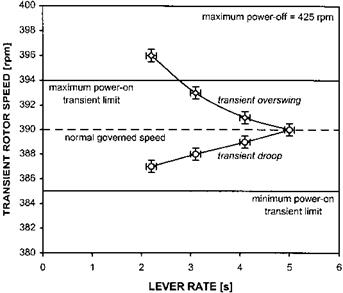
The operational effect of transient overswing is assessed by conducting mission tasks which require rapid lever lowering such as practise forced landings, entry to quickstops, and re-masking manoeuvres. Excessive overswing will lead to excursions above the rotor speed limit or may lead to restrictions on the rate of lever lowering that the pilot is able to employ. Of course there may be other reasons for imposing limitations on the rate of lowering the collective lever such as excessive coupling in the pitch or yaw axes. In addition, the need to respect the minimum normal acceleration limits may prevent the pilot from lowering the lever rapidly. Figure 7.8 shows a combined plot illustrating the effect of lever rate of transient droop and overswing.

7.4.6.3 Governor stability

While transient droop and overswing testing is an examination of the governor system characteristics during rapid changes in power demand, governor stability testing is concerned with the reaction of the system to high frequency, small amplitude collective lever inputs. If the system has low bandwidth then the engines will not be able to respond to higher frequency collective inputs leading to rotor speed variations occurring out of phase with lever movements. On the other hand if the gain of the droop law is too great it is possible to drive the system unstable.

image187

Fig. 7.8 Transient droop/overswing test data.

The test method is to conduct a collective frequency sweep using small amplitude ( + 10% to +20%) collective inputs starting at a low frequency. The frequency is gradually increased to a maximum frequency of approximately 2 Hz: higher frequencies are unlikely to be generated during operational tasks. Any tendency for the response of the engine(s) and rotor speed to become out of phase with the collective input is noted. The reaction of the governing system once the inputs are stopped is also observed to ensure that oscillations of the power system do not continue. Like all testing which involves high frequency control inputs considerable care is required to prevent fatigue damage to the aircraft. Significant lags in the torque indication system will also be highlighted in this testing. Following the frequency sweep tests, mission tasks that involve high frequency collective inputs are conducted. These may include positioning for a deck landing, precision landings, and setting down underslung loads.

Engine matching

In multi-engined installations each engine will typically operate to an individual droop law due to different mechanical tolerances within the engines and their control systems. To ensure that the maximum power is available from all the engines a means of power matching is usually provided. The pilot will normally match the engine torques but engine temperatures may also be used if they become the limiting variable. Pilots are sensitive to torque mismatches at all power settings as this can be the initial indication of an engine failure or governor malfunction. Consequently some automatic alerting systems use torque mismatches, above a certain threshold, as the trigger for activation of an engine failure warning. These have not proved popular due to the difficulty of eliminating false warnings.

Testing of static power matching can be combined with static droop testing by matching engine torques at a datum power setting, normally minimum power for rotors at pre-take off NR on the ground or maximum continuous torque in flight, and then noting the mismatch throughout the power range. Mismatches during rapid power changes are also documented during transient overswing and engine accelera­tion tests. The additional workload placed on the crew in dealing with power matching will determine if a deficiency exists. This will depend not only on the size of the mismatches but also on the characteristics of the manual power matching system. For example, an aircraft which suffers from a large power mismatch on take-off and has the manual matching control mounted off the flight controls may significantly increase the crew workload. For obvious reasons the engines must be correctly adjusted before these tests.

7.4.3 Transient droop, transient torque response and overswing

Once the static variation of NR with power setting has been established tests are made to determine the dynamic characteristics of the engine(s) and governing systems. Transient droop, transient torque response and overswing testing involves assessing how the power supply system reacts to sudden changes in power required.

7.4.6.1 Transient droop

The amount by which the NR droops following a rapid collective pitch increase depends on the rate of collective increase, the rotor inertia, the acceleration capabilities of the engine(s) and the speed of reaction of the engine(s) and rotor governing system. For the operational pilot a large amount of rotor droop following a collective lever pull could have serious consequences; it might not be possible to arrest a rate of descent as quickly as required and may also lead to problems with control response at low rotor speeds.

Testing transient droop involves collective lever pulls from a low power position to a high power position at incrementally increasing rates until a limiting factor is reached or a satisfactory result consistent with the aircraft role is obtained. The low power position should ideally equate to zero torque but depending on the design of the gearbox it may be necessary to ‘join the needles’ by matching the speeds of the power turbine(s) and the rotor to avoid damage to the transmission system. The higher collective position is chosen such that any torque spikes remain within the transient limits; typical values are collective positions that equate to 90% or 95% of maximum continuous torque. Some means is used to block the co-pilot’s collective to prevent the maximum test value being exceeded; this can either be the flight test engineer’s hand or a fixture held by him or her.

The test is conducted by setting the maximum collective position and establishing the block. The collective is then lowered to the low power position previously established. A slow collective ramp input is made over a period of at least 5 seconds until the collective contacts the block. The timing is achieved by one of the crew members conducting a cadence count. It is important for the control to be moved at a constant rate throughout the pull and no attempt should be made to vary the rate of application simply to meet the target time. In addition to noting the Nr droop, the maximum torque value and the maximum engine temperatures are recorded. The crew must also be alert for any sign of instability within the power system and for other effects such as large yaw rates occurring. If the test team conclude that it is safe to increase the rate of collective application then the test is repeated using a count reduced by one second. Although this incremental approach is the safest way of approaching rapid lever rates experience has shown that large variations in peak torque may occur with even small increases in collective rate.

Once the ‘academic’ tests have been completed a series of mission tasks should be flown which are designed to identify any problems with transient droop. These may include jump take-offs, baulked landings, recovery from flight idle glide and the final stages of a quick stop. For naval aircraft, landings are made onto a heaving deck or this task is simulated. Aircraft with collective anticipators fitted may have no droop problems with collective inputs, however, droop may occur with inputs made with the cyclic or yaw pedals. In these cases tests are also made of rapid rolling in forward flight and of rapid yaw inputs in the hover.

Static droop measurement

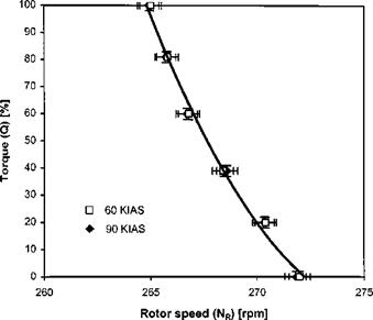
Measurement of static droop is achieved by setting the nominal rotor speed on the ground or in flight and noting the variation of Nr with power setting at a variety of airspeeds. For each test point the aircraft is flown accurately and the condition allowed to stabilize before data is recorded. For the zero airspeed point the NR value for a series of power settings is recorded as the aircraft is raised into an OGE hover and then higher powers are achieved during vertical climbs. If the aircraft has an avoid area then the OGE hover and vertical climbs are performed above the danger zone. An alternative to the zero airspeed point is to use the tethered hovering technique (Section 3.5.6.3) which will permit the full range of power settings to be tested without climbing. Forward flight tests are flown using a saw-tooth profile around the datum altitude starting at the power for level flight for the chosen airspeed. Static droop testing is often combined with aircraft performance and static stability testing. Test results are usually presented in the form of a plot of power or torque against NR for each speed condition, as shown in Fig. 7.7.

For aircraft without droop cancellation the rotor speed will depend only upon the power setting. The amount of droop will not be affected by the collective lever position and therefore a single test airspeed will be all that is required. For systems that

image186

Fig. 7.7 Static droop test data.

incorporate droop cancelling, airspeed becomes a factor as it will affect the collective position for any given power setting due to the different inflow through the rotor. In the same way the collective position will also be affected by the rates of climb and descent achieved for any given power setting which means that the aircraft weight will affect the results. To fully document the static droop of such a system requires, in theory, a large matrix of test points at various density altitudes, weights and airspeeds; in practice however, a zero airspeed, minimum power, and VH point at low and high density altitudes normally suffices.

To the operational pilot static droop is never a desirable system characteristic. A large amount of static droop at high power settings will cause the tail rotor to operate at a reduced RPM and may lead to a loss of tail rotor effectiveness. Some systems require the pilot to compensate for droop by providing a manual ‘beep’ control. However, this has the serious disadvantage of requiring the pilot or co-pilot to direct his or her attention inside the cockpit for relatively long periods often at critical moments such as when transitioning to the hover. Even if the pilot is not required to compensate and the aircraft handling is not affected, large variations in NR with power demand are a distraction for the pilot and should be considered to be a deficiency. A series of role manoeuvres that requires large changes in power setting such as lifting external loads or rapid transitions to the hover are flown to determine the effect of any droop.

Engine(s) and rotor starting

Tests are made to assess the procedure for starting the engine(s) and engaging the rotor; this will include determining the starting envelope. Eventually, successful engine starting will have to be demonstrated throughout the anticipated operational range of environmental temperatures. Tests include internal battery starts of cold-soaked engines and restarts of engines with high residual temperatures. The airborne re-light envelope and recommended airspeed are also established for each engine in a multi-engine aircraft. This re-light envelope is often smaller than the aircraft operational flight envelope as at high altitude there may insufficient air density to windmill the engine properly or insufficient oxygen to ensure adequate ignition. The drain on the electrical system caused by starting an engine can sometimes result in other aircraft systems being affected, for example, the AFCS can drop out, lighting circuits can be switched off and navigation systems can close down. For normal ground starts none of these effects may matter as the engines are usually started before these systems are engaged, however, for airborne starts the implications may be serious and must be investigated.

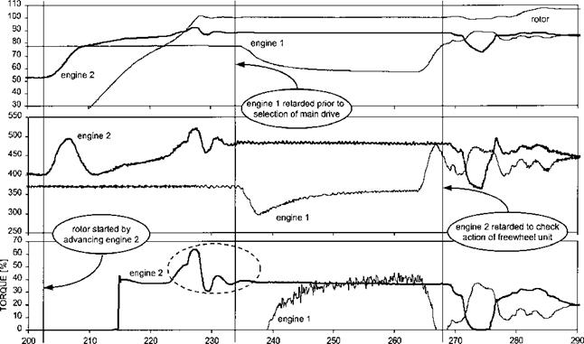
The starting sequence is assessed to determine if the actions required of the pilot are easy to perform and the order is logical. Many engine starting sequences are extremely complex and require a high degree of concentration, although with the advent of FADEC systems this problem has become less common. In addition to a subjective opinion on the starting process, quantitative data is collected on time to light-up, rate of oil pressure rise, and the temperature rise profile. This data is normally presented in reports in the form of time histories and an example is shown in Fig. 7.6. The maximum rate at which the rotor can be accelerated to the normal operating RPM is found by incrementally increasing the rate at which the throttle is advanced until a limiting condition is reached. The total time required to complete a start from commencing the pre-start checks to being ready for take-off is also established; for certain roles, such as search and rescue, air ambulance and special forces operations, this time may be a major factor in determining the acceptability of the aircraft.

Подпись: TEMPERATURE [°С] SPEED [%]
Подпись: Systems Testing 321

TIME [S]


Fig. 7.6 Engine data – time history of rotor start (note the torque oscillation, caused by FPT governor, as rotor first reaches normal operating speed).


image185

The engine and rotor shutdown procedure is also assessed to determine if it is easy to perform. The lack of a rotor brake or an inefficient one may constitute a deficiency in some roles where having the rotor turning for prolonged periods at low RPM may create a hazard to the aircraft or personnel. In addition, any requirement for long engine cooling periods at ground idle may be considered a deficiency.

ENGINE AND ROTOR GOVERNING

The engine and rotor governing system of a helicopter is designed to regulate the flow of fuel to the engine(s) to provide the pilot with the correct amount of power at a suitable rotor speed for the demands being made with the flight controls. In addition the system is required to provide control over the starting and stability of the combustion process. The aim of the test programme therefore, is to assess the operation of the governing system over as wide a range as possible of operationally relevant conditions. Since the main focus of this book is flight testing, the qualification testing of gas turbine powerplants [7.10] will not be covered in any detail. The results from flight tests are used to make recommendations for improvements to the system as well as defining system limitations. These limitations include restrictions on the rate of conducting power changes, residual engine temperature limits for starting, and altitude and airspeed limits for engine re-lights whilst airborne.

7.4.1 Trials planning

To conduct a full engine and governing system assessment a comprehensive instru­mentation package is fitted to the aircraft. The parameters recorded typically include:

• the state of the aircraft (airspeed, altitude, OAT, RoC/RoD, sideslip);

• the position of relevant aircraft controls (collective lever, SSL or ‘beep’ control, throttle);

• the state of the engine(s) (compressor speed, power turbine speed, engine temper­atures, engine pressures, rotor speed, positions of any anti-surge devices).

For trials involving digital engine control systems the inputs to the digital engine control unit (DECU) and the outputs from it are recorded. For more limited trials where it is not practical to fit a full instrumentation suite, it is possible to obtain useful data by using a video camera trained on the instrument panel. As part of the trials planning process the environmental conditions required and how they will be achieved need to be decided upon. For example, it is necessary to conduct engine starting tests with the aircraft both hot – and cold-soaked. This can either be achieved by placing the aircraft in an environmental chamber or by conducting the tests during cold weather and/or hot and high trials in suitable locations.

Before the trial begins the aircraft is checked to make sure that the engine(s) and the rotor are set-up in accordance with the manufacturer’s instructions. This may include such tests as determining the engine power output and FIG or autorotative descents to establish that the rotor has been correctly rigged. As the trial progresses these settings are checked periodically to make sure that engine and rotor have not shifted excessively from these baseline settings. Usually the engine(s) are bench tested and calibrated both prior to the trial and post-trial.

7.4.2 Cockpit assessment

The controls and indicators associated with the engine(s) and rotor governing system are assessed in the same way as any cockpit assessment. Particular emphasis is placed on the sensible grouping of items so that tasks such as engine and rotor starting or stopping are easy to accomplish. For example, it is common to find that the start switch is remote from the igniter indication which is also remote from the engine temperature gauge; this can make it difficult for the pilot to monitor the start adequately and may lead to late intervention during a hot start. Emergencies that require the use of the engine(s) and rotor controls are also studied to determine if all the controls can be reached and operated easily. For these evaluations the normal and emergency drills contained in the aircraft checklists are commonly used.

Managing pressure errors

The Royal Navy developed one method of compensating for the deficiencies of airspeed indicators at low airspeeds. When Westland Lynx helicopters were taking off from ships’ decks it was observed that the pilot did not have reliable airspeed indications until the aircraft had achieved in excess of 40 KIAS. This was due to a combination of the low dynamic pressure itself and the downwash of the main rotor at high power settings. Consequently the pilot had no reliable means of judging when the helicopter had reached an airspeed from which it would be able to perform a flyaway in the event of an engine failure since the minimum speed for the flyaway was typically below 40 kts. The solution to this problem was to determine the relationship between airspeed and time when flying a standard take-off technique. This then allowed pilots to use time rather than airspeed to determine at which point a flyaway should be made rather than ditching conducted. The pilot was provided with charts that accounted for aircraft weight, OAT, height above water, and windspeed thus producing a critical time, known as Tcrit. Provided that the aircraft had passed Tcrit and the total

image184

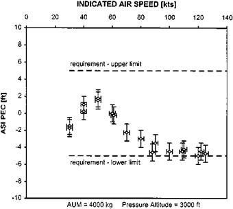
Fig. 7.5 Airspeed indicator PEC data (obtained using the trailing pitot-static method).

intervention time did not exceed two seconds, then pilots were assured of being able to fly away with a minimum separation of ten feet from the surface.

Another area of the flight envelope where PEs can have a major influence is during instrument approaches. When involved in a precision approach, such as a GCA, the pilot is told the decision height (DH) for the runway he intends to approach. To this figure he may need to add the helicopter type allowance (see below) and a further increment depending on his instrument rating. In the UK it is usual to reduce the DH reported by the air-traffic controller by 50 ft. This takes account of the fact that the helicopter can transition to a lower speed, ultimately the hover, rather than having to perform an ‘S’ manoeuvre to align with the runway centreline before touching down. In the UK the minimum is 150 ft for a CAT 1 approach (a FW minimum of 200 ft reduced by 50 ft). This minimum may also be considered as being made up of a height to avoid obstacles, the dominant obstacle allowance, and a factor to account for both errors in the pitot-static system and the anticipated height loss involved in a missed – approach procedure, the aircraft allowance. Work done some 25 years ago [7.9] identified that for medium to large twin-engined helicopters using a 3° glide slope the aircraft allowance (AA) was typically 100 ft. This allowance was the summation of a number of factors and error sources associated with the static pressure system that feeds the altimeter. One source was the maximum permissible variation in the PEs across a fleet of similarly equipped aircraft.

The actual PEs associated with a particular model of rotorcraft in descending flight are dealt with separately in the helicopter type allowance (HTA). Although the runway DH plus the instrument rating factor is usually reported back to the GCA controller the effect of the HTA remains within the cockpit. Thus the HTA represents the increment in pressure height required to ensure that the true pressure height at the decision point does not fall below the minimum allowed. The HTA is determined by measuring the altimeter PEs whilst performing a GCA profile, typically 80 to 100 kts with a 500 ft/min RoD. This basic PE is increased by a factor to account for the stiction and lag in the instrument associated with responding to a steadily increasing static pressure, provided these errors have not already been included in the AA.

AFTTC method

This method was developed in the early seventies at Edwards AFB, and involved the aircraft performing consecutive turns through a common airmass. It was dubbed the ‘cloverleaf’ method due to the pattern the aircraft described in the sky. The aircraft flew three passes at 120° apart from each other at the same indicated airspeed. Although pre-dating the first method by some margin it fell out of favour in its original form as it required radar tracking which resulted in it being expensive and difficult to co-ordinate from the ground. However, with the advent of GPS, this method has now become much more economical. Recently Olson [7.8] re-introduced the method and presented a non-linear mathematical solution that removes the need to fly orthogonal headings.

7.3.2 Data presentation

Test results are reduced and presented in the form of IAS against altitude or airspeed pressure error correction (PEC) and it is this correction that must be added to the

image183

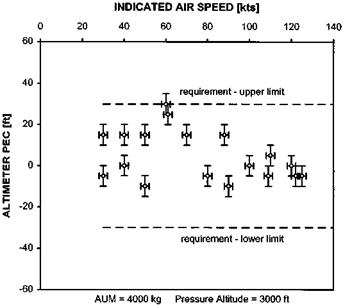
Fig. 7.4 Altimeter PEC data (obtained using the trailing pitot-static method).

indication to yield the calibrated value. Level, climbing and autorotative flight PECs are normally presented on one graph for one aircraft configuration. Airspeed indicator PECs with sideslip are normally plotted in the form of PEC against sideslip angle for specific flight conditions (airspeed and power) for one aircraft configuration. Figures

2.4 and 7.5 show test data obtained for a medium sized twin engine helicopter and compares it with the specification requirements.

GPS methods

Since the advent of GPS, several different flight test techniques have been developed to make use of this system in determining pressure errors. There are good reasons why GPS is attractive for such tests:

• No special equipment is needed, such as trailing cones, kinetheodolites, cameras.

• There is no need to keep and maintain a calibrated pacer aircraft.

• A surveyed ground course is not required.

• Flying close to the ground is not required.

• There is no requirement for radar tracking.

The largest drawback to these methods is that results typically show high data scatter. The paragraphs below outline two multi-track GPS techniques that have been developed.

7.3.6.1 NTPS method

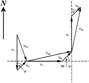
In this method, three orthogonal headings are flown at the same IAS and altitude (see Fig. 7.3). The ground speed is read about 15 to 20 seconds after the IAS is stable,

image182

Fig. 7.3 Flight path for PEC measurement using GPS (assuming constant wind strength and direction).

allowing time for the GPS data to stabilize. From the three groundspeeds, the wind velocity, wind direction and true airspeed can be determined using basic trigonometry [7.7]. The resulting angle for the wind direction is the angle clockwise from north, assuming that the original heading was south. For other initial headings, the wind angle must be adjusted. Knowledge of wind direction and velocity is not strictly necessary to determine the PEC as they can be eliminated from the equations. However, a review of the wind data might prove useful in determining if the test data is reasonable.

Trailing pitot-static method

Freestream total and static pressures can be measured by suspending pitot and static sources on a cable attached to a suitable strong point fitted with an emergency jettison facility. Pressures are transmitted through two tubes to the helicopter where they are converted to accurate pressure altitudes and equivalent airspeeds by sensitive calibrated instruments. Since the pressures are transmitted to the helicopter prior to conversion to airspeeds and altitudes, no systematic error is introduced by trailing the sources below the helicopter. The system is usually calibrated in a wind tunnel prior to installation and the cable is around two rotor diameters in length. The trailing pitot – static (TPS) typically comprises a streamlined body equipped with a drag cone or tail fins to align it with the relative airflow. Pitot and static ports are placed at suitable locations on the body. A suspension point over the CG incorporates a swivel so that the cable cannot exert a moment on the body. Test instruments in the aircraft cabin display, once their own instrument errors have been taken into account, calibrated airspeed and true pressure altitude. Tubes connect the trailing sources to the test instruments via breakaway links and the support cable is attached to the underslung load hook or, if none is available, to a special-to-type release bracket. Experience has shown that it is possible to deploy a TPS from the aircraft cabin in low-speed flight if OGE hover performance is not available at take-off.

As before, level flight runs are maintained for approximately one minute with the observer recording both TPS and aircraft IAS and pressure altitude every 15 seconds. For climbs and descents measurements are made over a height band 500 ft either side of the nominal test altitude. The same parameters as for level flight are measured on entering the test band, at the test altitude and when leaving the test band. For accurate data it is important that the run is started at sufficient height above or below the test band to ensure that the helicopter is fully stabilized (speed, power, NR and rate of climb/descent) when the test band is entered.

Formation method

In the formation method, the test aircraft is flown in concert with another (pace) aircraft whose pressure errors are known. This method has several advantages over others:

• Both level flight altimeter and ASI pressure errors can be determined simultaneously.

• The method can be used for climbs and descents.

• Since the PE calibration is made by comparing the altimeter and ASI readings of the two aircraft in the same air mass there is no need to calculate TAS.

The pace aircraft is normally equipped with calibrated pitot and static systems fed from boom mounted sensors to eliminate the effect of main rotor downwash. The pitot head is usually swivel-mounted to reduce the effects of a and p.

The distance between the test aircraft and the pace aircraft is carefully chosen so that it is sufficiently close to aid holding a steady station yet far enough away to ensure no mutual interference. A spacing equal to two rotor diameters of the larger helicopter is often used. Once again the required test conditions are maintained for about one minute while the observers in both aircraft record IAS and height every 15 seconds. Clearly IAS comparisons can only be made if the pace aircraft can cover the speed range of the test helicopter. However, this is not necessary for static errors as the test helicopter can be flown past the pace aircraft (or vice-versa) and altimeter readings compared. As with any formation flying, a comprehensive briefing, which deals with all aspects of normal and emergency operations, communications and safety procedures, is essential. There is often a temptation to fly too close together, which must be resisted if good data is to be gathered with minimum risk to either aircraft. Since the pilot will spend the majority of the time ‘eyes out’, the co-pilot or FTE usually assumes the responsibility for monitoring aircraft systems as well as advising the pilot of slip-ball position. It is important that all changes in flight path are made gently with due consideration to any performance differences between test and pace aircraft otherwise time will be wasted unnecessarily in re-establishing a tight formation.

Reduction of data gathered using the formation method is perhaps the simplest of any method currently used to determine pressure errors. After adjustment of all readings from both the pace and the test aircraft, to take account of instrument errors, the pressure errors are found simply by subtraction. If the airspeed and altitude from the pace aircraft come from test gauges fitted to a boom mounted system operating in the freestream there is usually no need to be concerned with the effect of the pressure field surrounding the aircraft. So:

*V = (ASIR + instrument error)pace — (ASIR + instrument error)test

*hP = (AltR + instrument error)pace — (AltR + instrument error)test