Category MECHANICS. OF FLIGHT

Lateral stability

Lateral and directional stability will first be considered separately; then we shall try to see how they affect each other.

To secure lateral stability we must so arrange things that when a slight roll takes place the forces acting on the aeroplane tend to restore it to an even keel.

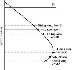
In all aeroplanes, when flying at a small angle of attack, there is a resistance to roll because the angle of attack, and so the lift, will increase on the down­going wing, and decrease on the up-going wing. But this righting effect will only last while the aeroplane is actually rolling. It must also be emphasised that this only happens while the angle of attack is small; if the angle of attack is near the stalling angle, then the increased angle on the falling wing may cause a decrease in lift, and the decreased angle on the other side an increase; thus the new forces will tend to roll the aeroplane still further, this being the cause of auto-rotation previously mentioned (Fig. 8.11).

But the real test of stability is what happens after the roll has taken place.

Longitudinal dihedral

The tail plane is usually set at an angle less than that of the main planes, the angle between the chord of the tail plane and the chord of the main planes being known as the longitudinal dihedral (Fig. 9.3). This longitudinal dihedral is a practical characteristic of most types of aeroplane, but so many considerations enter into the problem that it cannot be said that an aeroplane which does not possess this feature is necessarily unstable longitudinally. In any case, it is the actual angle at which the tail plane strikes the airflow, which matters; therefore we must not forget the downwash from the main planes. This downwash, if the tail plane is in the stream, will cause the actual angle of attack to be less than the angle at which the tail plane is set (Fig. 5.6). For this reason, even if the tail plane is set at the same angle as the main planes, there will in effect be a longitudinal dihedral angle, and this may help the aeroplane to be longitudinally stable.

Longitudinal dihedral

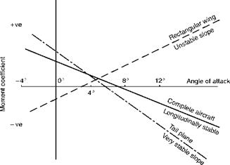
Fig 9.2 Pitching moment coefficient about centre of gravity Wing, tail plane and complete aircraft.

Longitudinal dihedral

Fig 9.3 Longitudinal dihedral angle

Suppose an aeroplane to be flying so that the angle of attack of the main planes is 4° and the angle of attack of the tail plane is 2°; a sudden gust causes the nose to rise, inclining the longitudinal axis of the aeroplane by 1°. What will happen? The momentum of the aeroplane will cause it temporarily to con­tinue moving practically in its original direction and at its previous speed. Therefore the angle of attack of the main planes will become nearly 5° and of the tail plane nearly 3°. The pitching moment (about the centre of gravity) of the main planes will probably have a nose-up, i. e. unstable tendency, but that of the tail plane, with its long leverage about the centre of gravity, will defi­nitely have a nose-down tendency. If the restoring moment caused by the tail plane is greater than the upsetting moment caused by the main planes, and possibly the fuselage, then the aircraft will be stable.

This puts the whole thing in a nutshell, but unfortunately it is not quite so easy to analyse the practical characteristics which will bring about such a state of affairs; however the forward position of the centre of gravity and the area and leverage of the tail plane will probably have the greatest influence.

It is interesting to note that a tail plane plays much the same part, though more effectively, in providing longitudinal stability, as does reflex curvature on a wing, or sweepback with wash-out of incidence towards the tips.

When the tail plane is in front of the main planes (Fig. 5E) there will prob­ably still be a longitudinal dihedral, which means that this front surface must have greater angle than the main planes. The latter will naturally still be at an efficient angle, such as 4°, so that the front surface may be at, say, 6° or 8°. Thus it is working at a very inefficient angle and will stall some few degrees sooner than the main planes. This fact is claimed by the enthusiasts for this type of design as its main advantage, since the stalling of the front surface will prevent the nose being raised any farther, and therefore the main planes will never reach the stalling angle.

In the tail-less type, in which there is no separate surface either in front or behind, the wings must be heavily swept back, and there is a ‘wash-out’ or decrease in the angle of incidence as the wing tip is approached, so that these wing tips do, in effect, act in exactly the same way as the ordinary tail plane (Figs 5C and 5D).

Longitudinal stability

We shall start with longitudinal stability, since this can be considered indepen­dently of the other two. In order to obtain stability in pitching, we must ensure that if the angle of attack is temporarily increased, forces will act in such a way as to depress the nose and thus decrease the angle of attack once again. To a great extent we have already tackled this problem while dealing with the pitching moment, and the movement of the centre of pressure on aerofoils. We have seen that an ordinary upswept wing with a cambered aerofoil section cannot be balanced or ‘trimmed’ to give positive lift and at the same time be stable in the sense that a positive increase in incidence produces a nose-down pitching moment about the centre of gravity.

The position as regards the wing itself can be improved to some extent by sweepback, by wash-out (i. e. by decreasing the angle of incidence) towards the wing tips, by change in wing section towards the tips (very common in modern types of aircraft), and by a reflex curvature towards the trailing edge of the wing section.

But it is not only the wing that affects the longitudinal stability of the air­craft as a whole, and in general it can be said that this is dependent on four factors –

1. The position of the centre of gravity, which must not be too far back; this is probably the most important consideration.

2. The pitching moment on the main planes; this, as we have seen, usually tends towards instability, though it can be modified by the means men­tioned.

3. The pitching moment on the fuselage or body of the aeroplane; this too is apt to tend towards instability.

4. The tail plane – its area, the angle at which it is set, its aspect ratio, and its distance from the centre of gravity. This is nearly always a stabilising influence (Fig. 9.2).

Stability and control

Meaning of stability and control

The stability of an aeroplane means its ability to return to some particular con­dition of flight (after having been slightly disturbed from that condition) without any efforts on the part of the pilot. An aeroplane may be stable under some conditions of flight and unstable under other conditions. For instance, an aeroplane which is stable during straight and level flight may be unstable when inverted, and vice versa. If an aeroplane were stable during a nose-dive, it would mean that it would resist efforts on the part of the pilot to extricate it from the nose-dive. The stability is sometimes called inherent stability. Note that, nowadays, some military combat aircraft are deliberately made to be inherently unstable, as this increases their manoeuvrability, and can reduce drag. This requires a sophisticated automatic artificial stabilisation system, which has to be totally reliable. Because of the potentially disastrous conse­quences of system failure, inherent instability is not permitted on civil aircraft, but with adequate safeguard it is possible to relax the level of stability com­pared to older types, and this has benefits in terms of reduced drag. To the pilot, the artificial stabilisation system makes the aircraft feel and handle as though it were stable.

Stability is often confused with the balance or ‘trim’ of an aircraft, and the student should be careful to distinguish between the two. An aeroplane which flies with one wing lower than the other may often, when disturbed from this attitude, return to it. Such an aeroplane is out of its proper trim, but it is not unstable.

There is a half-way condition between stability and instability, for, as already stated, an aeroplane which, when disturbed, tends to return to its orig­inal position is said to be stable; if, on the other hand, it tends to move farther away from the original position, it is unstable. But it may tend to do neither of these and prefer to remain in its new position. This is called neutral stab­ility, and is sometimes a very desirable feature.

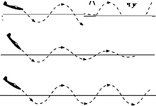
Figure 9.1 illustrates some of the ways in which an aeroplane may behave when it is left to itself. Only a pitching motion is shown; exactly the same con­siderations apply to roll and yaw, although a particular aeroplane may have quite different stability characteristics about its three axes. The top diagram shows complete dead-beat stability which is very rarely achieved in practice. The second is the usual type of stability, that is to say an oscillation which is gradually damped out. The steady oscillation shown next is really a form of neutral stability, while the bottom diagram shows the kind of thing which may easily occur in certain types of aircraft, an oscillation which steadily grows worse. Even this is not so bad as the case when an aeroplane makes no attempt to return but simply departs farther and farther away from its original path. That is complete instability.

The degree of stability may differ according to what are called the stick – fixed and stick-free conditions; in pitching, for instance, stick-fixed means that the elevators are held in their neutral position relative to the tail plane, whereas stick-free means that the pilot releases the control column and allows the elevators to take up their own positions.

Another factor affecting stability is whether it is considered – and tested – under the condition of power-off or power-on. On modern aircraft the engine thrust can be comparable with or even greater than the airframe weight and therefore may significantly influence the stability.

Stability and control

4

Control means the power of the pilot to manoeuvre the aeroplane into any desired position. It is not by any means the same thing as stability; in fact, the two characteristics may directly oppose each other.

The stability or control of an aeroplane in so far as it concerns pitching about the lateral axis is called longitudinal stability or control respectively.

Stability or control which concerns rolling about the longitudinal axis is called lateral stability or control.

Stability or control which concerns yawing about the normal axis is called directional stability or control.

Before we attempt to explore this subject any further we feel it is our duty to warn the reader that the problems involved in the consideration of stability and control of aeroplanes are considerable. Any attempt at ‘simple’ expla­nation of such problems may, at the best, be incomplete and possibly incorrect. Readers need have no fear of the mathematics, as we shall not even attempt to tackle them, but they must be prepared, if and when they acquire greater knowledge of the subject from more advanced works, to readjust their ideas accordingly.

After this very necessary apology we will try to explain, at any rate, the practical considerations which affect stability and control.

Manoeuvrability

Before leaving the subject of manoeuvres we ought to mention that the inertia of an aeroplane – or, to be more correct, the moment of inertia of the various parts – will largely determine the ease or otherwise of handling the machine during manoeuvres. Without entering into the mathematical meaning of moment of inertia, we can say that, in effect, it means the natural resistance of the machine to any form of rotation about its centre of gravity. Any heavy masses which are a long distance away from a particular axis of rotation will make it more difficult to cause any rapid movement around the axis; thus masses such as engines far out on the wings result in a resistance to rolling about the longitudinal axis; and a long fuselage with large masses well forward or back will mean a resistance to pitching and yawing.

Can you answer these?

See if you can answer these questions about the various manoeuvres which an aeroplane can perform –

1. What are the six degrees of freedom of an aeroplane?

2. Why is there a definite limit to the smallness of the radius on which an aeroplane can turn?

3. Two aircraft turn through 360° in the same time, i. e. at the same rate of turn, but the radius of turn of one is twice that of the other. Will they have the same angle of bank? If not, which will have the greater?

4. Explain the difference between a gliding and climbing turn from the point of view of holding off bank.

5. Why does an aeroplane spin?

For solutios see Appendix 5.

Numerical examples on manoeuvres will be found in Appendix 3.

Manoeuvrability

Fig 8D Manoeuvres

(By courtesy of the Lockheed Aircraft Corporation, USA)

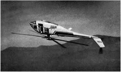
A rigid-rotor helicopter performing aerobatic manoeuvres.

Aerobatics

The usual aerobatics are loops, spins, rolls, sideslips, and nose-dives, to which may be added upside-down flight, the inverted spin, and the inverted loop. The manoeuvres may also be combined in various ways, e. g. a half loop followed by a half roll, or a half roll followed by the second half of a loop.

There are many reasons why aerobatics should be performed in those types of aircraft which are suitable for them. They provide excellent training for accuracy and precision in manoeuvre, and give a feeling of complete mastery of the aircraft, which is invaluable in all combat flying. They may also be used for exhibition purposes, but modern aircraft are so fast and the radius on which they can turn or manoeuvre is so large that, in many ways, they provide less of a spectacle than older types. Not least, aerobatics increase the joy and sensations of flight to the pilot himself – not quite so much to other occupants of the aircraft!

The movements of the aeroplane during these aerobatics are so complicated that they baffle any attempt to reduce them to the terms of simple mechanics and, indeed, to more advanced theoretical considerations, unless assumptions are made which are not true to the facts.

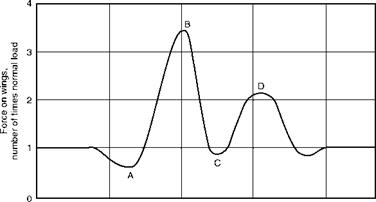
Figs 8.8 and 8.9 (overleaf) show the approximate path travelled by a slow type of aircraft during a loop and the corresponding ‘accelerometer’ diagram which shows how the force on the wings varies during the manoeuvre. From this it will be seen that, as in many manoeuvres, the greatest loads occur at the moment of entry. Notice also that even at the top of the loop the load is very little less than normal – that is to say, that the pilot is sitting firmly on his seat in the upward direction, the loads will still be in the same direction relative to the aircraft as in normal flight, and our plumb bob will be hanging upwards!

Aerobatics

0 112 1 minute

4 2 4

Accelerometer record

Fig 8.9 Accelerometer diagram for a loop

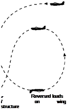
Only in a bad loop will the loads at the top become negative, causing the loads on the aircraft structure to be reversed and the pilot to rely on his straps to prevent him from falling out.

Simple theoretical problems can be worked out on such assumptions as that a loop is in the form of a circle or that the velocity remains constant during the loop, but the error in these assumptions is so great that very little practical information can be obtained by attempting to solve such problems, and it is much better to rely on the results of practical experiments.

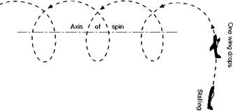
A Spin (Fig. 8.10) is an interesting manoeuvre, if only for the reason that at one time there stood to its discredit a large proportion of all aeroplane acci­dents that had ever occurred. It differs from other manoeuvres in the fact that the wings are ‘stalled’, – i. e. are beyond the critical angle of attack, and this accounts for the lack of control which the pilot experiences over the move­ments of the aeroplane while spinning; it is, in fact, a form of ‘auto-rotation’ (Fig. 8.11), which means that there is a natural tendency for the aeroplane to rotate of its own accord. This tendency will be explained a little more fully when dealing with the subject of control at low speeds in the next chapter. In a spin the aeroplane follows a steep spiral path, but the attitude while spinning may vary from the almost horizontal position of the ‘flat’ spin to the almost vertical position of the ‘spinning nose-dive’. In other words the spin, like a gliding turn or steep spiral is composed of varying degrees of yaw, pitch and roll. A flat spin is chiefly yaw, a spinning nose-dive chiefly roll. The amount of pitch depends on how much the wings are banked from the horizontal. In general, the air speed during a spin is comparatively low, and the rate of descent is also low. Any device, such as slots, which tend to prevent stalling, will also tend to minimise the danger of the accidental spin and may even make it impossible to carry out deliberately. The area and disposition of the

Подпись: Fig 8.11 Cause of auto-rotation Подпись: Fig 8.10 A spin

Aerobatics

Подпись: MANOEUVRES 249

Aerobatics

Aerobatics

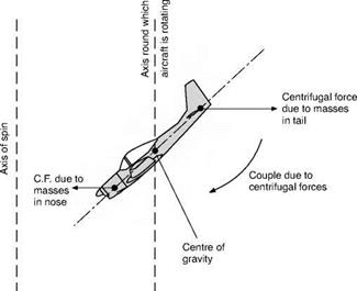
Fig 8.12 Tendency of a spin to flatten owing to centrifugal force fin, rudder, and tail plane exert considerable influence on the susceptibility of the aeroplane to spinning.

Many of the terrors of a spin were banished once it was known just what it was. We then realised that in order to get out of a spin we must get it out of the stalled state by putting the nose down, and we must stop it rotating by applying ‘opposite rudder’. In practice, the latter is usually done first, because it is found that the elevators are not really effective until the rotation is stopped. The farther back the centre of gravity, and the more masses that are distributed along the length of the fuselage, the flatter and faster does the spin tend to become and the more difficult is it to recover. This flattening of the spin is due to the centrifugal forces that act on the masses at the various parts of the aircraft (Fig. 8.12). A spin is no longer a useful combat manoeuvre, nor is it really a pleasant form of aerobatics, but since it is liable to occur acciden­tally, pilots are taught how to recover from it.

During a roll (Fig. 8.13) the aeroplane rotates laterally through 360°, but the actual path is in the nature of a horizontal corkscrew, there being varying degrees of pitch and yaw. In the so-called slow roll the loads in the 180° pos­ition are reversed, as in inverted flight, whereas in the other extreme, the barrel roll, which is a cross between a roll and a loop, the loads are never reversed.

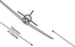
In a sideslip (Fig. 8.14) there will be considerable wind pressure on all the side surfaces of the aeroplane, notably the fuselage, the fin and the rudder, while if the planes have a dihedral angle the pressure on the wings will tend to bring the machine on to an even keel. The sideslip is a useful manoeuvre for

Aerobatics

90° roll


Fig 8.13 A roll

losing height or for compensating a sideways drift just prior to landing, but, as already mentioned, modern types of aircraft do not take very kindly to sideslipping. The small side area means that they drop very quickly if the sideslip is at all steep, and the directional stability is so strong that it may be impossible to hold the nose of the machine up (by means of the rudder), and the dropping of the nose causes even more increase of speed.
Aerobatics

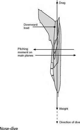
A nose-dive is really an exaggerated form of gliding; the gliding angle may be as great as 90° – i. e. vertical descent – although such a steep dive is rarely performed in practice. If an aeroplane is dived vertically it will eventually reach a steady velocity called the terminal velocity. In such a dive the weight is entirely balanced by the drag, while the lift has disappeared. The angle of attack is very small or even negative, there is a large positive pressure near the leading edge on the top surface of the aerofoil, tending to turn the aeroplane on to its back, and this is balanced by a considerable ‘down’ load on the tail plane (Fig. 8.15, overleaf). In such extreme conditions the terms used are apt to be misleading; for instance, the ‘down’ load referred to is horizontal, while the lift, if any such exists, will also be horizontal. The terminal velocity of modern aeroplanes is very high, and it makes little difference whether the engine is running or not. They lose so much height in attaining the terminal velocity that, in practice, it is doubtful whether it can ever be reached. As was only to be expected, the problems which accompany the attainment of a speed near to the speed of sound first made themselves felt in connection with the nose-dive, especially at high altitudes. At that time these compressibility effects were a special feature of nose-diving, but there was one consoling feature – as one got nearer the earth, terminal velocities were lower (owing to the greater

і

і

і

Aerobatics

density), and the speed of sound was higher (owing to the higher temperature). So if one got into trouble high up, there was always a chance of getting out of it lower down. But nowadays, when more and more aircraft can exceed the speed of sound in level flight, and when compressibility troubles are no longer associated with fears of the unknown, these ideas are out of date, and the whole subject of flight at and above the speed of sound will be considered in Chapters 11 and 12.

The nose-dive, and the pulling-out of a nose-dive, are two entirely different problems, and the latter has already been fully dealt with.

Inverted manoeuvres

Real upside-down flight (Fig. 8.16) is not so often attempted as is commonly supposed, and should be distinguished from a glide in the inverted position,

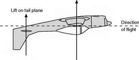
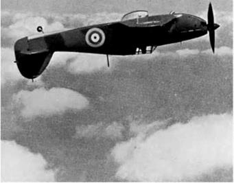
which does not involve problems affecting the engine. If height is to be main­tained during inverted flight, the engine must, of course, continue to run and this necessitates precautions being taken to ensure a supply of fuel and, with a piston engine, the proper functioning of the carburettor. The aerofoil will be inverted, and therefore, unless of the symmetrical type, will certainly be inef­ficient; while in order to produce an angle of attack, the fuselage will have to be in a very much ‘tail-down’ attitude. The stability will be affected, although some aircraft have been more stable when upside-down than the right way up, and considerable difficulty has been experienced in restoring them to normal flight. In spite of all the disabilities involved, some aeroplanes are capable of maintaining height in the inverted position (Fig. 8C, overleaf).

The inverted spin is in most of its characteristics similar to the normal spin; in fact, in some instances pilots report that the motion is more steady and therefore more comfortable. As in inverted flight, however, the loads on the aeroplane structure are reversed and the pilot must rely on his straps to hold him in the machine.

The inverted loop, or ‘double bunt’, in which the pilot is on the outside of the loop (Fig. 8.17, overleaf), is a manoeuvre of extreme difficulty and danger. The difficulty arises from the fact that whereas in the normal loop the climb to the top of the loop is completed while there is speed and power in hand and engines and aerofoils are functioning in the normal fashion, in the inverted loop the climb to the top is required during the second portion of the loop, when the aerofoils are in the inefficient inverted position. The danger is incurred because of the large reversed loads and also because of the physiolog­ical effects of the pilot’s blood being forced into his head. It was a long time before this manoeuvre was successfully accomplished, and once it had been, so many foolhardy pilots began to attempt it – often with fatal results – that it had to be forbidden, except under very strict precautions and regulations.

Lift on wings due to angle of attack

Aerobatics

Aerobatics

Fig 8C Inverted flight (By courtesy of ‘Flight’)

Подпись: Normal Подпись: У Reversed loads / on wing structure

And to illustrate upside-down flight, the Hurricane of the Second World War; note the tail-down attitude usually associated with inverted flight.

‘Bumpy’ weather

In addition to the loads incurred during definite aerobatics, all aircraft are required to face the effects of unsteady weather conditions. Accelerometer records show that these may be quite considerable, and they must certainly be reckoned with when designing commercial aircraft. Where aeroplanes are, in any case, required to perform aerobatics, they will probably be amply strong enough to withstand any loads due to adverse weather. The conditions which are likely to inflict the most severe loads consist of strong gusty winds, hot sun, intermittent clouds, especially thunder clouds in which there is often consider­able turbulence, and uneven ground conditions; a combination of all these factors will, almost certainly, spell a ‘rough passage’. The turbulence and up- currents that may be encountered in severe thunderstorms and in cumulo-nimbus clouds can sometimes be such as to tax the strength of the aeroplane and the flying skill of the pilot.

Controls on steep banks

The turning of an aeroplane is also interesting from the control point of view because as the bank becomes steeper the rudder gradually takes the place of the elevators, and vice versa. This idea, however, needs treating with a certain amount of caution because, in a vertical bank for instance, the rudder is nothing like so powerful in raising or lowering the nose as are the elevators in normal horizontal flight. Incidentally, the reader may have realised that a ver­tical bank, without sideslip, is theoretically impossible, since in such a bank the lift will be horizontal and will provide no contribution towards lifting the weight. If it is claimed that such a bank can, in practice, be executed, the explanation must be that a slight upward inclination of the fuselage together with the propeller thrust provides sufficient lift.

This only applies to a continuous vertical bank in which no height is to be lost; it is perfectly possible, both theoretically and practically, to execute a turn in which, for a few moments, the bank is vertical, or even over the vertical. In the latter case the manoeuvre is really a combination of a loop and a turn.

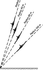
Generally speaking, the radius of turn can be reduced as the angle of bank is increased, but even with a vertical bank there is a limit to the smallness of the radius because, quite apart from the question of side-slipping, the lift on the wings (represented by CL. jpV2. S) must provide all the force towards the centre, i. e. m. Г-/Г or WV2lgr.

Thus WW/gr = CL. ipV2. S

or r = 2W/(CL. pS. g)

Now, in straight and level flight the stalling speed (V) is given by the equation W = L = CL max. CL. ipV2. S

If we substitute this value of W into our formula for the radius we get

Г = (2 . CL max. CL. |pV2. S)/(CL. pS. g) i. e. r = (V2/g) X (CLmax/CL)

This shows that the radius of turn will be least when CL is equal to CL max, i. e. when the angle of attack is the stalling angle, and radius of turn = V2/g. It is rather interesting to note that the minimum radius of turn is quite inde­pendent of the actual speed during the vertical banks; it is settled only by the stalling speed of the particular aeroplane. Thus, to turn at minimum radius, one must fly at the stalling angle, but any speed may be employed provided the engine power is sufficient to maintain it. In actual practice, the engine power is the deciding factor in settling the minimum radius of turn whether in a ver­tical bank or any other bank, and it must be admitted that it is not usually possible to turn on such a small radius as the above formula would indicate.

This formula applies to some extent to all steep turns and shows that the aeroplane with the lower stalling speed can make a tighter turn than one with a higher stalling speed. (We are referring, as explained above, to the stalling speed in straight and level flight.) But in order to take advantage of this we must be able to stand the g’s involved in the steep banks, and we must have engine power sufficient to maintain turns at such angles of bank.

Other problems of turning

In order to get into a turn the pilot puts on bank by means of the ailerons, but once the turn has commenced the outer wing will be travelling faster than the inner wing and will therefore obtain more lift, so he may find that not only is it necessary to take off the aileron control but actually to apply opposite aileron by moving the control column against the direction of bank – this is called holding off bank.

An interesting point is that this effect is different in turns on a glide and on a climb. On a gliding turn the whole aircraft will move the same distance downwards during one complete turn, but the inner wing, because it is turning on a smaller radius, will have descended on a steeper spiral than the outer wing; therefore the air will have come up to meet it at a steeper angle, in other words the inner wing will have a larger angle of attack and so obtain more lift than the outer wing. The extra lift obtained in this way may compensate, or more than compensate, the lift obtained by the outer wing due to increase in velocity. Thus in a gliding turn there may be little or no need to hold off bank.

In a climbing turn, on the other hand, the inner wing still describes a steeper spiral, but this time it is an upward spiral, so the air comes down to meet the inner wing more than the outer wing, thus reducing the angle of attack on the inner wing. So, in this case, the outer wing has more lift both because of vel­ocity and because of increased angle, and there is even more necessity for holding off bank than during a normal turn.

Another interesting way of looking at the problem of gliding and climbing turns is to analyse the motion of an aircraft around its three axes during such turns. In a flat turn, i. e. a level turn without any bank, the aircraft is yawing only. In a banked level turn, the aircraft is yawing and pitching – in the extreme of a vertically banked turn it would be pitching only. But in a gliding or climbing turn the aircraft is pitching, yawing and rolling. In a gliding turn it is rolling
inwards; in a climbing turn, outwards. The inward roll of the gliding turn causes the extra angle of attack on the inner wing, the outward roll of the climbing turn on the outer wing. Many people find it difficult to believe this. If the reader is in such difficulty conviction may come from one of two methods; which will suit best will depend upon the reader’s temperament. The mathematically – minded may like to analyse the motion in terms of the following (Fig. 8.7) –

The rate of turn of the complete aeroplane (about the vertical), Q.

The angle of bank of the aeroplane, в.

The angle of pitch of the aeroplane, ф.

A little thought will reveal the fact that the

Rate of yaw = Q. cos ф. cos в.

Rate of pitch = Q. cos ф. sin в.

Rate of roll = £2 . sin ф.

Translating this back into English, and taking one of the extreme examples, when в = 0, i. e. no bank, and 0 = 0, i. e. no pitch, cos в and cos ф will be 1, sin в and sin ф will be 0.

.’. rate of yaw = £2 = rate of turn of complete aeroplane.

Rate of pitch and rate of roll are zero. All of which we had previously decided for the flat turn.

Подпись: Rate of turn Q Подпись: Angle of * inclination of longitudinal axis

The reader (mathematically-minded) may like to work out the other extremes such as the vertical bank (в = 90°) or vertical pitch (ф = 90°), or better still the more real cases with reasonable values of в and ф.

Fig 8.7 Gliding turns

Notice that the rate of roll depends entirely on the angle of pitch, i. e. the inclination of the longitudinal axis to the vertical – if this is zero, there is no rate of roll even though the aircraft may be descending or climbing.

What about the reader who does not like mathematics? Get hold of a model aeroplane, or, failing this, a waste-paper basket and spend a few minutes making it do upward and downward spirals; some people are convinced by doing gliding and climbing turns with their hand and wrist – and their friends may be amused in watching!

At large angles of bank there is less difference in velocity, and in angle, between inner and outer wings, and so the question of holding off bank becomes less important; but much more difficult problems arise to take its place.

First, though, let us go back to the other extreme and consider what is called a ‘flat turn’, i. e. one that is all yaw and without any bank at all.

Very slight turns of this kind have sometimes been useful when approaching a target for bombing purposes, but otherwise they are in the nature of ‘crazy flying’, in other words, incorrect flying, and good pilots always try to keep their sideslip indicator in the central position. Actually flat turns are rather dif­ficult to execute for several reasons. First, the extra velocity of the other wing tends to bank the aeroplane automatically; secondly, the lateral stability (explained later) acts in such a way as to try to prevent the outward skid by banking the aeroplane; thirdly, the side area is often insufficient to provide enough inward force to cause a turn except on a very large radius; fourthly, the directional stability (also explained later) opposes the action of the rudder and tends to put the nose of the aircraft back so that it will continue on a straight path. Taking these four reasons together, it will be realised that an aeroplane has a strong objection to a flat turn!

Modern aircraft have a small side surface and if this is coupled with good directional stability, for the last two reasons particularly, a flat turn becomes virtually impossible. So much is this so that it is very little use applying rudder to start a turn, the correct technique being to put on bank only.

Correct and incorrect angles of bank

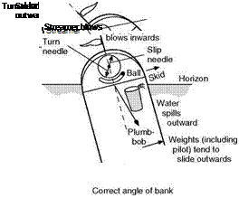
We have so far assumed that the aeroplane is banked at the correct angle for the given turn. Fortunately the pilot has several means of telling whether the bank is correct or not (Fig. 8.6, overleaf), and since the methods help us to understand the mechanics of the turn, it may be as well to mention them here.

A good indicator is the wind itself, or a vane, like a weather cock, mounted in some exposed position. In normal flight and in a correct bank the wind will come from straight ahead (neglecting any local effects from the slipstream); if the bank is too much, the aeroplane will sideslip inwards and the aeroplane, and pilot if he is in an open cockpit, will feel the wind coming from the inside of the turn, whereas if the bank is too small, the wind will come from the outside of the turn, due to an outward skid on the part of the aeroplane.

Another indication would be a plumb-bob hung in the cockpit out of contact with the wind. In normal flight this would, of course, hang vertically; during a correct bank it would not hang vertically, but in exactly the same pos­ition relative to the aeroplane as it would in normal flight, i. e. it would bank with the aeroplane. If over-banked the plumb-line would be inclined inwards; if under-banked, outwards from the above position. This plumb-bob idea, in the form of a pendulum, forms the basis of the sideslip indicator which is pro­vided by the top pointer of the so-called turn and bank indicator. The pointer is geared so as to move in such a way that the pilot must move the control

Correct and incorrect angles of bank

Angle of bank too small

Fig 8.6 Effects of correct and incorrect angles of bank

column away from the direction of the pointer, this being the instinctive reac­tion. Sometimes a curved transparent tube containing a metal ball is used, and again the control column must be moved away from the indication given on the instrument. It is interesting to note that in early aeroplanes the slip indi­
cator was, in effect, a spirit level, the tube being curved the opposite way and with a bubble (in liquid) instead of the ball; the pilot was then told to ‘follow the bubble’ – not the instinctive reaction. Nowadays such simple mechanical devices are being replaced by electronic or digital displays which neverthless often mimic the apearance of the older instruments. Figure 8.6 shows how a tumbler full of water would not spill even when tilted at 80° in a correct bank; if the bank were too small it would spill outwards over the top lip of the tumbler!

Lastly, during a correct bank the pilot will sit on his seat without any feeling of sliding either inwards or outwards; in fact, he will be sitting tighter on his seat than ever, his effective weight being magnified in the same proportions as the lift so that if he weighs 800 N in normal flight he will feel that he weighs 8000 N when banking at 84°! If he over-banks he will tend to slide inwards, but outwards if the bank is insufficient.

Loads during a turn

It will be clear from the figures that the lift on the wings during the turn is greater than during straight flight; it is also very noticeable that the lift increases considerably with the angle of bank. This means that structural com­ponents, such as the wing spars, will have to carry loads considerably greater than those of straight flight.

Mathematically, W/L = cos в, or L = W/cos в

i. e. at 60° angle of bank, lift = 2W, stalling speed, 85 knots (44m/s) at 70° angle of bank, lift = 3W, stalling speed, 104 knots (53m/s)

£ ‘

Loads during a turn

Fig 8.5 Correct angles of bank Air speed 60 knots (31 m/s)

at 75° angle of bank, lift = 4W, stalling speed, 120 knots (62 m/s)

at 84° angle of bank, lift = 10W, stalling speed, 190 knots (98 m/s)

These figures mean that at these angles of bank, which are given to the nearest degree, the loads on the wing structure are 2, 3, 4, and 10 times respectively the loads of normal flight. This is simply our old friend g again, but in this instance it is certainly better to talk in terms of load than of g because the accelerations, and the corresponding loads, are in a horizontal plane while the initial weight is vertical; it is no longer a question of adding by simple arith­metic.

Whatever the angle of bank, the lift on the wings must be provided by CL. ypV2 . S. It follows, therefore, that the value of CL . ypV2 . S must be greater during a turn than during normal flight, and this must be achieved either by increasing the velocity or increasing the value of CL. Thus it follows that the stalling speed, which means the speed at the maximum value of CL, must go up in a turn; as before it will go up in proportion of the square root of the wing loading, and the stalling speeds corresponding to the various angles of bank are shown in the table assuming, as for the pull-out of a dive, a stalling speed in level flight of 60 knots (31 m/s). These are all fairly steep banks; for banks up to 45° or so the loads are not serious, there is no danger of blacking out, and the increase of stalling speed is quite small – even so, it needs watching if one is already flying or gliding anywhere near the normal stalling speed, and suddenly decides to turn. At steep angles of bank we have to contend not only with the considerable increase of stalling speeds but with all the same problems as arose with the pull-out, i. e. blacking out, injury to pilot and crew, and the possibility of structural failure in the aircraft. It may seem curious that the angle of bank should be the deciding factor, but it must be remembered that the angle of bank (provided it is the correct angle of bank) is itself dependent on the velocity and radius of the turn, and these are the factors that really matter. In the history of fighting aircraft the ability to out­turn an opponent has probably counted more than any other feature, and from this point of view the question of steeply banked turns is one of paramount importance. An aspect of this question which must not be forgotten is that of engine power; steep turns can only be accomplished if the engine is powerful enough to keep the aeroplane travelling at high speed and at large angles of attack, perhaps even at the stalling angle. The normal duties of the engine are to propel the aeroplane at high speed at small angles of attack, or low speed at large angles of attack, but not both at the same time. The need for extra power in steeply banked tight turns has resulted in a technique in which the pilot embarking on such a manoeuvre suddenly applies all the power available.