Category Principles of Helicopter Aerodynamics Second Edition

Unsteady Attached Flow

A prerequisite in any unsteady aerodynamic theory is the ability to model accu­rately the unsteady airloads at the blade element under attached flow conditions. In the first instance, the most elementary level of approximation is to consider incompressible, 2-D flow. This avoids the need to model the wake from other blades (a problem considered in detail in Chapter 10) and allows convenient analytical and semi-analytical mathematical solutions to be incorporated into the rotor analysis. However, the helicopter rotor analyst is still faced with several compromises. First, the assumptions and limitations of any model must be properly assessed and understood. For example, neglecting the compressibility of the flow is not readily justified for rotor problems. This justification requires that not only must the local free stream Mach number be low, but the frequency of the source of unsteady effects must be small compared to the sonic velocity, that is, the product ooc/a <$C 1, where a is the speed of sound. This means that the characteristic reduced frequency must also be small. The reduced frequency can be written as к = a>c/2Ma, so that Mk <$C 1 to justify the assumption of incompressible flow. Second, any model must be written in a mathe­matical form that can be coupled into the structural dynamic model of the rotor system. For example, in some cases it may be desirable to write the aerodynamic model at each blade element as sets of ordinary differential equations. Third, because the blade element unsteady aerodynamic model is contained within radial and azimuthal integration loops, computational time considerations are important, and this alone can limit the allowable level of sophistication possible with any mathematical model of unsteady aerodynamics.

The most fundamental approach to the modeling of unsteady aerodynamic effects is through an extension of steady, 2-D thin-airfoil theory. This gives a good level of analysis of the problem and provides considerable insight into the physics responsible for the underlying unsteady behavior. Results for unsteady airfoil problems have been formulated in both the time domain and the frequency domain, primarily by Wagner (1925), Theodorsen (1935),

Kiissner (1935), and von Karman & Sears (1938). These solutions all have the same roots in incompressible, unsteady thin-airfoil theory and give exact analytic (closed-form) solutions for the pressure distribution (hence, the forces and pitching moments) for different forcing conditions (i. e., for perturbations in AoA or an imposed nonuniform vertical distribution of chordwise velocity). While these methods are valid for 2-D and incompressible flows, and were primarily intended for fixed-wing aeroelastic applications, they have also formed the foundation for several extensions to subsonic compressible flow and also to specific types of rotating-wing problems. For example, one extension of Theodorsen’s theory was developed by Loewy (1957), which is a solution that approximates the effects of the shed wake vorticity below the rotor, as laid down by the blade and by other blades.

The unsteady compressible (subsonic) thin-airfoil problem has also received consider­able attention – see, for example, Lomax et al. (1952) and Lomax (1968). Even though in some cases the local flow may have an incident Mach number that may be low, the product Mk must still be much less than unity if the incompressibility of the flow is to be justified. Because the governing equation in a compressible flow is the hyperbolic wave equation compared to the elliptic nature of Laplace’s equation for incompressible flow [see Karamcheti (1966)], unsteady aerodynamic theories cannot be obtained in a corresponding exact, convenient analytical form. There are, however, some limited exact solutions and numerical solutions available. These can be used to great advantage in the development of semi-analytic or semi-empirical methods for unsteady subsonic compressible flows, which are formulated in the spirit of the classical incompressible theories but are still computa­tionally practical enough to be included within helicopter rotor analyses.

Reduced Frequency and Reduced Time

F / pV с V шс

pV2c2 (і a ‘ V

Подпись: f (Re, M, k), Подпись: (8.1)

One important parameter used in the description of unsteady aerodynamics and unsteady airfoil behavior is the reduced frequency. This parameter is used to characterize the degree of unsteadiness of the problem. It can be shown that the reduced frequency appears when nondimensionalizing the Navier-Stokes equations. Alternatively, it can be shown using dimensional analysis that the resultant force F on an airfoil of chord c, oscillating at angular frequency со in a flow of velocity V, can be written in functional form as

the proof of which is the basis of Question 8.1. As noted previously in Section 7.3, the resultant force, F, depends on the Reynolds number, Re, and the Mach number, M, but now the reduced frequency, k, of the flow is a third parameter to be considered. The reduced frequency is normally defined in terms of the airfoil semi-chord, b = c/2, so that

Подпись: (8.2)cob coc ~V ~ 2V

For к = 0, the flow is steady. For 0 < к < 0.05, the flow can be considered quasi­steady; that is, unsteady effects are generally small, and for some problems they may be neglected completely. Usually flows with characteristic reduced frequencies of 0.05 and above are considered unsteady, and the unsteady terms in the governing equations cannot be routinely neglected. Problems that have characteristic reduced frequencies of 0.2 and above are considered highly unsteady, and the unsteady terms, such as those associated with acceleration effects, will begin to dominate the behavior of the airloads.

Подпись: 1.05£2c 2 x 0.75£2R Подпись: 2.8 c ~R~’ Подпись: (8.3)

For a helicopter rotor in forward flight the reduced frequency at any blade element is an ambiguous parameter because the local sectional velocity (which appears in the denomi­nator of the reduced frequency expression) is constantly changing. However, a first-order approximation for к can give useful information about the degree of unsteadiness found on a rotor and the necessity of modeling unsteady aerodynamic effects in any form of analysis. Consider first the unsteady effects induced by rigid blade flapping, for which it has been shown in Section 4.7 that the first flap frequency is about 1.05 £2 for an articulated rotor. Then the reduced frequency, k75, at the 75% radius location (r = 0.75) will be

assuming for simplicity that the local velocity at the blade element is just the rotational veloc­ity, rQR. For a helicopter rotor with a blade aspect ratio R/c > 10, then k7s > 0.07, which
is in the unsteady range. Also, because the reduced frequencies increase further inboard on the blade owing to the lower values of local sectional velocity, к may become relatively large. Consider further the first elastic torsion mode, which is typically about 3-4£2. In this case, at the tip the reduced frequency associated with airloads generated by torsional dis­placements is in excess of 0.2. At these reduced frequencies, there is a significant amplitude and phasing introduced into the airloads by the effects of the unsteady aerodynamics, and the modeling of unsteady aerodynamics is critical if erroneous predictions of the airloads are to be avoided.

It should be appreciated that the previous reduced frequency calculations are only very approximate and serve only to illustrate the potential significance of unsteady effects and the need to model such effects in predicting the airloads in rotor problems. For quantification of more transient problems, the concept of a single reduced frequency in terms of characterizing the degree of unsteadiness of the problem begins to lose its significance. Under these circumstances it is normal to use reduced time, s, where

Reduced Frequency and Reduced Time(8.4)

which represents the relative distance traveled by the airfoil through the flow in terms of airfoil semi-chords during a time interval t. It has been found useful to characterize many of the events occurring in unsteady aerodynamics, such as dynamic stall or blade encounters with blade tip vortices, in terms of a reduced time parameter.

Concepts of the Blade Wake

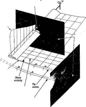
The wake from the rotating blade comprises, in part, a vortical shear layer or vortex sheet, with a concentrated vortex formed at the blade tip. The vortex sheet is comprised of vorticity with vectors aligned mainly normal to and parallel to the trailing edge of the

Blade motion


Подпись: PitchingПодпись:Подпись: Trim (iow freq., high amp.)

Подпись: Blade torsion (high freq., high amp.) Подпись: Blade bending (High freq., low amp.)

Flapping

Flowfield structure

Подпись: PeriodicПодпись:

Подпись: Discrete vortices (multiple, high amp.) Подпись: Wake distortion (multiple, low amp.) Подпись: Fuselage flowfield (multiple, low amp.)

Aperiodic

Подпись:Concepts of the Blade WakePitch (from blade controls & torsional response)
Plunge or heave (from blade flapping)

Time-varying incident velocity or lead-lagging biaae or horizontal gusts

Concepts of the Blade Wake

Vertical gusts (rotor wake, tip vortices, airframe effects, etc.)

Concepts of the Blade Wake

Figure 8.2 Decomposition of unsteady aerodynamic forcing terms at the blade element level.


Circulation "bound to the blade


Blade lift distribution


і uruuiem vonex sneet behind the blade


Roll up of tip vortex


Trailed

vorticity


Tip vortex from previous blade


Figure 8.3 Schematic showing the wake and tip vortex rollup behind a single blade and the interaction with the vortex from another blade.


Concepts of the Blade Wake

blade, as shown in Fig. 8.3, which is a schematic reconstruction of the wake behind a rotor blade using both flow field measurements and flow visualization. The strength of the former component (the trailed vorticity) is related to the spanwise gradient of lift (circulation, Г) on the blade (i. e., to 3Г/3r), whereas the latter component (the shed vorticity) is related to the time rate of change of lift on the blade (i. e., to ЭГ/dt). Experiments with rotors have shown that the blade tip vortices are almost fully rolled-up within only a few degrees of blade rotation. Because the aerodynamic loading on the blades is biased toward their tips, the tip vortex is of high overall strength with significant induced velocities.

While the fundamental process of the blade wake and tip vortex formation is similar to that found with a fixed wing, one obvious difference with helicopter tip vortices is that they are curved and so they experience a self-induced effect. Another complication with helicopter rotors is that the wakes and tip vortices from other blades can lie close to each other and to the plane of blade rotation and so have large induced effects on the blade lift distribution. Because of these self – and mutually induced effects, the problem of calculating the detailed airloads over the rotor disk is quite formidable. Miller (1964) has examined the higher harmonics of the rotor loading in forward flight and has concluded that the effects of the trailed wake (tip vortices) are generally more important than the shed wake; only for very low advance ratios or for hove^ do the effects of the “returning” shed wake or the shed
wake from other blades seem to be important. However, the effects of the “near” shed wake (that is, the wake vorticity immediately behind each blade) on the blade from which it was generated were found to be important under all flight regimes. These observations suggest that the overall aerodynamic environment at the blade (specifically, the quasi-steady angle of attack at the blade element) is determined mainly by the trailed wake (tip vortex) system. In general, unsteady aerodynamic effects are relatively local and are a consequence of the time history of the vorticity contained in the shed wake immediately behind each blade. Such observations often permit simplified forms of mathematical analysis to be pursued, without substantial loss of accuracy in predicting the unsteady airloads on the rotor.

Sources of Unsteady Aerodynamic Loading

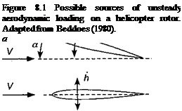
Figure 8.1 summarizes the various sources of unsteady effects that may affect the blade airloads. The AoA environment of a typical blade element is the resultant of a combination of forcing from collective and cyclic blade pitch, twist angle, elastic torsion, blade flapping velocity, and elastic bending. The induced downwash effects from the trailed wake system and the locally high velocity field perturbations produced by discrete tip vortices are also of primary importance, and their effects on the airloads must be considered if the unsteady aerodynamics effects on the rotor are to be fully understood and predicted.

At the blade element level, the various effects described in Fig. 8.1 can be decomposed into perturbations to the local AoA and velocity field, as shown in Fig. 8.2. At low an­gles of attack with fully attached flow, the various sources of unsteady effects manifest primarily as moderate amplitude and phase variations relative to the quasi-steady airloads. However, at higher angles of attack when time-dependent flow separation from the airfoil may be involved, a phenomenon that has become known as dynamic stall may occur. This phenomenon is manifest by large overshoots in the values of the lift, drag, and pitching moment relative to the quasi-steady stall values. Dynamic stall is also accompanied by much larger phase variations in the unsteady airloads as a result of significant hysteresis in the flow developments; that is, the values of the airloads at the same AoA may be very different depending on whether the flow is separating or reattaching. As will be discussed in Chapter 9, the amplitude and phase effects produced by the stalled airloads can lead to various aeroelastic problems on the rotor that may seriously limit its performance compared to that assumed or predicted on the basis of making quasi-steady flow assumptions.

Unsteady Airfoil Behavior

The addition of the dimension “time” to steady aerodynamics has far-reaching effects, both practical and theoretical. There is the practical necessity for coping with many important problems involving nonsteady phenomena such as nutter, buffeting, transient flows, gusts, dynamic response in flight, maneuvers, and stability. Apart from the many applications, theoretical nonsteady aerodynamics embraces and sheds light on the realm of steady aerodynamics and introduces interesting new methods.

I. E. Garrick (1957)

Подпись: 8.1Introduction

The confidence levels in the design of new helicopters are greatly improved by the ability to predict accurately the aerodynamic behavior of the rotor system at all comers of the operational flight envelope. One difficulty and uncertainty in this process is to fully account for unsteady aerodynamic effects, especially when the helicopter is in high-speed forward flight and during flight maneuvers. In the previous chapter, the quasi-steady aerodynamic characteristics of rotor airfoils have been discussed in detail. Yet, these attributes alone are not necessarily the best indicator as to whether a given airfoil will operate successfully in the rotor environment or will meet the requirements of a given rotor design. The next level of consideration is to examine unsteady aerodynamic effects and to strive to assess their potential impact on the prediction of the airloads and performance of helicopter rotors.

In the context of rotor airloads prediction, the mathematical modeling of unsteady airfoil behavior is one of formidable complexity. While the absence of significant flow separation reduces somewhat the complexity of the problem, a complete understanding of unsteady airfoil behavior even in attached flow has not yet been obtained. The additional problem of dynamic flow separation[27] is still the subject of ongoing research, and completely satisfactory predictive models of the problem have not yet been developed. This is particularly true for the rotor case, where the rotor blades encounter a broad spectrum of unsteady effects from a number of different sources. The most obvious are the excursions in AoA resulting from blade flapping and pitch control inputs. The additional effects of the rotor wake, with its embedded concentrated tip vortices, lead to regions of the rotor disk that can experience large perturbations in AoA over very short time scales. The problems are compounded by the 3-D effects found at the blade tips, which can be locally transonic during forward flight. Therefore, the problems of defining accurately the unsteady aerodynamic flow field on the rotor is really rather formidable.

The principal focus of the present chapter is to describe the key physical features and techniques for modeling the unsteady aerodynamic effects found on airfoils operating un­der nominally attached flow conditions away from stall. The essential physics of nonsteady airfoil problems can be observed from idealized 2-D experiments, and interpretations of

the behavior can be supported by theoretical or numerical models. The “classical” unsteady aerodynamic theories describing the observed behavior have formed the basis for many types of rotor analyses. The tools for the analysis of 2-D, incompressible, unsteady aerody­namic problems were laid down by 1940, with the extension to compressible flows complete by 1950. The most authoritative source documenting these theories is Bisplinghoff et al. (1955). Lomax and his colleagues (1952,1968) have provided a basis from which to develop linearized unsteady aerodynamic models applicable to compressible flows. The mathemat­ical elegance and computational simplicity of these linearized approaches are attractive to the helicopter rotor analyst. Although there have been a plethora of “new” unsteady aerodynamic theories developed over the years for helicopter applications, most still have their roots in the classical theories. Also, while the classical theories assume linearity in the airloads, the assumption of linearity can probably be justified for many of the problems encountered on the rotor, in practice. The proof of this latter statement is not always easy to justify, mostly because of other uncertainties in the problem such as those resulting from the rotor wake. The advent of nonlinear methods based on CFD solutions to the Euler and Navier-Stokes equations has provided new results that help the rotor analyst justify and define the limits of the parsimonious, linear models and may give guidance in developing improved and more practical unsteady aerodynamic models for future use in helicopter rotor blade airloads prediction, aeroelastic analysis, and rotor design.

Chapter Review

This chapter has described some basic aerodynamic characteristics of airfoil sec­tions and has provided a basis for assessing the potential impact of airfoil design and selection on helicopter rotor performance. Methods of geometrically defining airfoils have been described following the NACA approach of combining camberlines and thickness envelopes. This is justified because many of the airfoils used on current helicopter rotors have their origin in the NACA sections. Also, the ideas of combining loading distributions associated with thickness and camber allow the primary effects of geometric shape on the chordwise loading and overall aerodynamic characteristics to be assessed. However, the primary discussion in this chapter has been centered around published measurements of static airfoil characteristics. These results, while from more than one primary source, allow a good basis from which to compare airfoil behavior, and for the most part are considered relatively unbiased by the wind tunnel test facility or by testing techniques. For these latter reasons, it has not been considered fruitful to dwell on the relative merits of airfoils designed by the various competing helicopter manufacturers.

Airfoils designed for helicopter applications have traditionally been obtained through a long evolutionary process, in which various levels of theory and experimental measurements have been combined in the pursuit of airfoil shapes with higher values of maximum lift, better lift-to-drag ratios, lower pitching moments, and higher drag divergence Mach numbers. It has been shown that, in general, these requirements are conflicting, making the design of general purpose rotor airfoils extremely challenging. Instead, various families of airfoils have been developed and optimized to meet the specific needs of different parts of the rotor blade. For example, airfoils with high camber and moderate thickness, which give high values of maximum lift, are used between 60 and 85% of blade radius. Much thinner airfoils, perhaps even those with supercritical-like shapes, give relatively high drag divergence Mach numbers and have been designed for the tip region of the blade (>85%/?). The use of different airfoils along the blade is made easier today because of computer-aided design and composite manufacturing capability, which involves only small additional costs over a blade made with a single airfoil section.

The principles of integrating surface pressure and shear stress distributions to obtain lift, drag and pitching moment coefficients on airfoils have been reviewed. Representative airfoil characteristics have been discussed, along with the limits of conventional linearized theories in predicting this behavior. Because of the importance of low pitching moments in the design of helicopter airfoils, the principles of defining the aerodynamic center and center of pressure have been reviewed. The influence of Reynolds number and Mach number on airfoil characteristics have been highlighted. Although these parameters have both dependent and interdependent effects on airfoil behavior, it has been possible to isolate the basic effects and assess their significance on maximum lift and other important airfoil characteristics. Because the design of airfoils with high values of maximum lift can result in smaller and lighter rotors with lower solidity, the geometric shape of the airfoil and other factors affecting maximum lift have been discussed in detail.

While an improved understanding of airfoil characteristics will usually lead to an im­proved analysis capability of existing rotor designs, and may lead to new rotors optimized for greater performance in both hover and high-speed forward flight, the performance of the rotor cannot be completely parameterized on the basis of static (steady) considerations alone. Therefore, in the next two chapters, the important role of unsteady aerodynamics on the problem of airfoil behavior are discussed.

Effects of Damage on Airfoil Performance

Ballistic vulnerability is an important consideration for military helicopters be­cause they generally fly lower and slower than fixed-wing aircraft. Therefore, to minimize unexpected attrition of helicopter forces, any performance degradation must be minimized
and, if possible, prevented to ensure continued success on the battlefield. Compared to fixed-wing aircraft, however, helicopters have a much lower degree of system redundancy because the rotor itself provides all of the lift, propulsion and control. This means that any damage inflicted to the main or tail rotor systems is more likely to have serious con­sequences. Increased emphasis on improving survivability for US military helicopters has led to the Joint Live Fire (JLF) test program. These simulated live fire tests have helped to identify any especially vulnerable airframe components and aircraft subsystems early in the development cycle, so that potential problems can be rectified without incurring weight or cost penalties; see Foulk (1976) and Atkinson & Ball (1995).

While the use of modem composite materials give a high level damage tolerance to rotor blades, ballistic damage may still present significant problems in regard to the aerodynamic performance. A quantitative understanding of the aerodynamic effects of ballistic damage on the rotor system is, therefore, essential for the development and/or improvement of mathematical models representing these degraded aerodynamic effects in rotor analyses and to help assess reasonable risks in carrying on with a mission after the helicopter has been hit by a projectile. Unfortunately, the aerodynamic effects of blade damage will be a function of many interrelated parameters, including the location (chordwise and spanwise), physical nature of the damage and extent of damage. This makes the aerodynamic effects difficult to generalize. Yet it is clear that damage inflicted to the outboard sections of the blade are going to be aerodynamically more important on a rotor because of the high dynamic pressure in this area. At a minimum, a small damaged area on the blade may dramatically decrease section lift and increase drag. This will result in a loss of rotor thrust, increased rotor power requirements, the possibilities of premature blade stall, high control forces, and/or increased vibration levels. Even a minor performance degradation resulting from damage may incur much higher fuel consumption, and may seriously limit the ability of the helicopter to complete its assigned mission.

Some of the earliest recorded tests on the aerodynamic effects of ballistic damage was performed at NACA – see NACA (1936). This work examined the effects of machine gun and cannon fire on the lift and drag properties of fabric covered aircraft wings. More systematic experimental investigations were carried out by Reece (1952a, b). The results, which included measurements of the drag increase incurred by different damaged configu­rations, became the basis for later studies by Chang & Stearman (1980) and Westkaemper (1980). However, it is difficult to properly quantify ballistic damage effects on the aerody­namic characteristics of helicopter rotor blades because of the very 3-D and time-varying flow environment. Helicopter blade sections are often quite different physically and aero­dynamically to those used on fixed-wing aircraft, so it may not be appropriate to extrap­olate any known results to helicopters. Eastman (1993) has made some attempt to as­sess the aerodynamic effects on a UH-60 main rotor blade subject to ballistic damage. Leishman (1993, 1996) has made experimental measurements of the aerodynamic char­acteristics of series of helicopter blade sections with both simulated and actual ballistic damage. Other measurements on damaged airfoil sections have been conducted by Erwin & Render (2000).

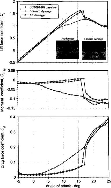
These tests have all revealed that ballistic damage significantly degraded the aerody­namic characteristics of the blade section, with a loss in lifting performance, changes in the pitching moment characteristics and a substantial increase in sectional drag. For example, Fig. 7.55 shows the measured aerodynamic characteristics of an undamaged SC1095-R8 airfoil section relative to two damaged specimens; one with simulated damage toward the leading edge and the other with damage near the trailing edge. The leading edge damaged blade section had a circular hole cut through the blade spar, whereas the damage at the

Effects of Damage on Airfoil Performance

Figure 7.55 Comparison of the lift, moment and drag coefficients of an undamaged airfoil section versus two specimens with simulated damage at the leading – and trailing-edges, respectively. Mach number = 0.3, Reynolds number = 2 x 10⁶. Data source: Leishman (1996).

trailing edge was cut into the paper honeycomb structure. It is apparent that damage near the leading edge of the section is more critical in terms of its effects on the aerodynamics than damage at the trailing edge. Notice that with leading edge damage, the lift-curve-slope decreases dramatically at approximately 6 degrees, yet the lift still continues to increase linearly after this point until stall occurs. This elbow in the lift-curve-slope is most likely

the result of increased flow from the lower surface up through the hole to the upper sur­face at higher angles of attack, that is, a “jet in a crossflow effect” – see Erwin & Render (2000). Flow visualization (inset in Fig. 7.55) has shown that this tends to fix the point of flow separation over the range from lower angles of attack through the stall angle. For increasing angles of attack this separation extends over large parts of the blade chord and span. Interestingly, while reaching a lower maximum lift coefficient than either the baseline or the specimen with trailing edge damage, the final stall AoA is at least 3° higher. The pitching moment variation suggests that leading edge damage caused an aft movement of the aerodynamic. center, which would probably not result in any adverse aeroelastic effects on the rotor. However, the drag for the forward damaged blade section is much larger than the baseline, growing from 1.4 times the baseline value at lower angles of attack to more than 2.5 times at higher angles of attack. This would have a very major effect on rotor performance and blade loads.

Very Low Reynolds Number Airfoil Characteristics

There has been much recent interest in understanding rotating wing airfoil charac­teristics at very low Reynolds numbers because of the generally low performance of existing micro air vehicles or MAVs (see Muller (2001) and discussion by Bohorquez et al. (2003), and also Section 6.14). The flow over airfoils at Reynolds numbers of less than 105 are gen­erally more complicated that those at higher Reynolds numbers because of stronger viscous effects, and as yet these effects are not well understood. The main problems include: 1. The susceptibility of a laminar boundary layer to separate under only mild adverse pressure gra­dients; 2. The formation of long laminar separation bubbles; 3. The thick boundary layers, high drag, and low maximum lift coefficients; and 4. The increased sensitivity of airfoil characteristics to surface condition and free-stream turbulence. Furthermore, at these low Reynolds numbers the airfoil characteristics tend to vary in a highly nonlinear manner with
respect to AoA, making modeling attempts much more challenging. It is in this regime that fundamental research in experimental fluid mechanics and modeling efforts using advanced numerical solutions to the Navier-Stokes equations are beginning to make an impact – see lvnuw ronnn

iTiuilvi J«

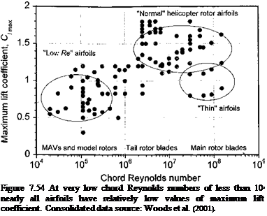
Besides the generally higher drag coefficients of airfoils that operate at low Reynolds numbers (see Fig. 7.4) this is accompanied by low maximum lift coefficients of 1.0 or less and low lift-to-drag ratios of 10 or less. This seriously impacts the overall flight perfor­mance of rotating-wing based MAVs – see Bohorquez et al. (2003) and Martin (2005). The results shown in Fig. 7.54 are consolidated data from many sources of low Reynolds number measurements that have been compiled by Woods et al. (2001) and show that values of C/max may be on average about half of the values found at higher Reynolds numbers, but perhaps with some exceptions. It would seem also that at these Reynolds numbers the aerodynamic performance of crude flat-plate types of airfoils are often surprisingly better that conventional airfoil profiles, raising many questions about what a low Reynolds number airfoil should really look like, especially for a rotor. The impact of higher airfoil drag coefficients and lower maximum lift coefficients generally translates into much lower values of rotor figure of merit; measured values of FM for rotating wing MAVs are typically in the range of 0.3 to 0.4 compared to values approaching 0.82 for a modem full-scale helicopter

Подпись: lift

Подпись: Figure 7.54 At very low chord Reynolds numbers of less than 105 nearly all airfoils have relatively low values of maximum lift coefficient. Consolidated data source: Woods et al. (2001).

rotor (Fig. 6.2). However, the ability to generate maximum

1.5 on rotating wings at very low Reynolds numbers seems possible based on the studies of Azuma & Yasuda (1989). For further information on the aerodynamics of airfoils at very low Reynolds numbers; see AGARD (1985), RAeS (1986), and Muller (2001).

Circulation Controlled Airfoils

Circulation controlled (CC) airfoils rely upon the Coanda effect to generate high lift independently of AoA. The Coanda effect has been introduced previously in Section 6.10.2 and is the tendency of a fluid issuing from a tangentially ejected jet to travel close to a
surface contour, even if the surface curvature diverges from the jet axis – see Newman

(1961) . Usually CC airfoils are elliptical or quasi-elliptical in shape, with well-rounded, almost blunt trailing edges. A balance of centrifugal force and reduced static pressure causes the thin jet to adhere to the blunt trailing edge. The jet is usually obtained by pressurizing a plenum inside the airfoil and ejecting flow out of a thin slot. Because of the high lift coefficients that can be attained with CC airfoils (often in excess of 2) they have been envisioned or applied for use on both fixed-wing and rotating-wing aircraft – see Wood & Neilsen (1986) and Reader et al. (1978).

Representative results for a CC airfoil at several free-stream Mach numbers are shown in Fig. 7.53 in terms of the jet momentum coefficient defined by

where m is the mass flow through the slot and V) is the jet velocity. At lower values of blowing the jet initially acts as an effective form of boundary layer control through flow entrainment on the upper surface of the airfoil. At higher blowing coefficients boundary layer control yields to super-circulation. At some point downstream of the slot the reduced static pressure and centrifugal force balance is ultimately lost (usually near where the jet velocity becomes sonic) and the jet detaches from the Coanda surface. This defines the maximum lift of the CC airfoil. The location of the jet detachment depends mainly on the strength of the jet, the slot geometry, the curvature of the Coanda surface, as well as the characteristics of the boundary layer prior to the slot.

The ideas of circulation control for application to a rotor were first investigated in depth by Cheeseman & Seed (1967). In the early 1980s, Kaman built and flight tested a CC rotor system on a HH-2D Seasprite, although only in hover and in low speed forward flight. Other applications of CC technology to rotorcraft are the ill-fated X-wing (see Linden & Biggers (1985) and Section 6.11.3) as well as the very successful NOTAR anti-torque system (see Section 6.10.2). However, while offering considerable possibilities when applied to rotor (either for either direct lift production or secondary lift control using higher harmonic

lift), the behavior of CC airfoils operating in a rotor environment is not well understood. In forward flight, a CC rotor encounters a time-varying flow environment in which both the AoA and local onset velocity vary periodically with azimuth position. Because the geometric pitch of the blade is generally held constant, jet blowing must be cyclically adjusted to for trim and control. This necessitates the modulation of the blade plenum pressure, and therefore, the jet blowing as a function of azimuth position. This is a highly unsteady aerodynamics problem.

The first theoretical work of CC airfoil aerodynamics was made by Kind (1968), Kind & Maull (1968), Dunham (1968), Dvorak & Kind (1979), and Soliman (1984). Dvorak & Kind (1979) incorporated integral and finite-difference boundary layer/jet mixing models into an external potential flow (surface singularity) model. Shrewsbury (1986) has used Navier-Stokes methods in the analysis of circulation controlled airfoils. Englar (1975) has shown results for pulsed blowing on a circulation controlled elliptical airfoil. Schmidt (1978) carried out experiments to examine the unsteady aerodynamic effects on an airfoil with a Coanda surface, reporting a transportation lag effect between the duct pressure and the blowing, as well as a decrease in lift augmentation ratio with increasing blowing frequency. A detailed bibliography of CC aerodynamics research through 1980 is given by Englar & Applegate (1984). The results of CC airfoil research as it applies to rotorcraft has been reviewed by Abramson et al. (1985).

Lorber et al. (1989) have investigated the unsteady aerodynamic behavior of an oscillating jet flap at a constant AoA and over a range of Mach numbers, albeit at limited blowing levels and at very low reduced frequencies. Ghee & Leishman (1990, 1992) and Zandieh & Leishman (1993) have investigated the behavior of a CC circular cylinder with periodic jet blowing operating in a steady free-stream. This work has also shown significant phase lags exist between the application of blowing and the buildup of the airloads. Furthermore, under some conditions unsteady blowing may cause sudden jet detachment, whereas this may not occur with steady blowing under the same free-stream conditions.

Computational work on modeling the behavior of CC airfoils under unsteady condi­tions is relatively scarce. Raghavan et al. (1988) and Sun & Wang (1989) used a surface singularity-boundary layer method for CC airfoils operating in an unsteady free-stream flow and with unsteady blowing, showing that CC airfoils will exhibit both a lift attenuation and a phase lag with respect to the blowing. While CC is clearly attractive because of the potentially high lift capability, the behavior of CC airfoils in an unsteady rotor environment is still not well understood. Nevertheless, CC airfoil concepts continue to be suggested for use on rotorcraft, but none have yet proved successful or practical.

High Angle of Attack Range

An understanding of the aerodynamic behavior of airfoils in the high AoA regime is important for predicting the adverse effects produced in the reverse flow regime on the rotor. In the reverse flow region, the AoA increases through stall beyond 90° as the direction of the relative flow vector now changes from the trailing edge toward the leading edge of the airfoil. Although the velocities and dynamic pressure are low in this region, the low maximum lift coefficients and high drag coefficients associated with flow separation may result in a higher overall parasitic power penalty (see also Section 5.5.10).

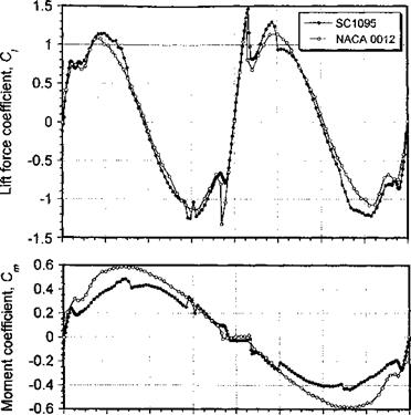
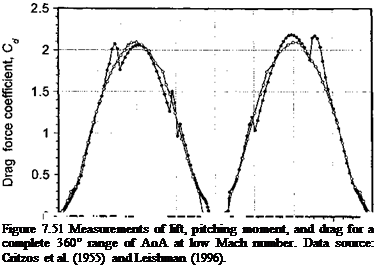
The aerodynamics of airfoils at extreme angles of attack beyond the normal static stall angle and in reversed flow have been measured by Lock & Townend (1925), Anderson (1931), Naumann (1942), Critzos et al. (1955), and Leishman (1996). All measurements are at low Mach numbers. Representative results are reproduced in Fig. 7.51, which shows the lift, pitching moment, and drag characteristics as a function of AoA. Although the airfoil shape makes some difference to the nature of the stall characteristic at positive and negative angles of attack and in reverse flow, when the flow becomes fully separated the results become mostly independent of airfoil shape and are close to the values for a flat-plate.

In the high AoA range, the quasi-steady lift coefficient can be modeled using

Ci = A sin2(o! — «о), (7.109) where A = 1.1 for the NACA 0012 and A = 1.25 for the SC 1095 when determined in a least-squares sense, with a being measured in degrees. An average value of 1.175 would seem reasonable for use with an arbitrary airfoil where the force coefficients are not known. For either airfoil, the center of pressure in the post stall regime moves close to mid-chord when or = 90° (i. e., xcp = 0.5). For the ranges 20° < (a — ccq) < 160° and —160° < (a — q? q) < —20° the center of pressure varies approximately linearly with a and can be represented by

xCp = 0.33 + 0.0019(a – or0) for 20° < (a – a0) < 160°, (7.110)

xcp = 0.33 – 0.0019(a – a0) for -160° < (a – a0) < -20°. (7.111)

Alternatively, the pitching moment in the post stall regime can be modeled directly using Cm — В sin(o: — «о) + C sin 2(ar — a0), (7.112)

High Angle of Attack Range

Подпись:0 F-i ■ – T–I ■’ ‘-і … ………………………………………… І ■ іЧфг-ч І… і, т-^
-180 -135 -90 -45 0 45 90 135 180

Angie of attack-deg.

where В = —0.5 and C = 0.11 are the averages for the two airfoils, which would seem appropriate choices for an arbitrary airfoil. Finally, the drag can be modeled using

Cd = D + E cos 2(a — «о), (7.113)

with D = 1.135 and E = —1.05 for both airfoils.

Angle of attack – deg.

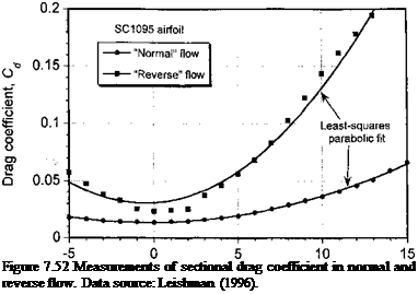
Подпись: Figure 7.52 Measurements of sectional drag coefficient in normal and reverse flow. Data source: Leishman (1996).

It becomes harder to model empirically the aerodynamic characteristics in the reverse flow regime. This can be seen if the drag coefficient in “normal” and “reverse” flow is examined in detail, as shown in Fig. 7.52. While the drag in normal flow is accurately represented by a simple parabolic fit, this is less applicable for the case of reverse flow. Notice that in this case the minimum drag is approximately double the minimum drag in normal flow’. Also, notice that the drag increases much more rapidly as the AoA is increased to either positive or negative values. Because the drag in reverse flow exhibits a “bucket” region, it is apparent that a parabolic fit to the measured data is less accurate in this case.

The forgoing discussion is based on the assumption that the flow in the reverse flow region is quasi-steady, but this may not necessarily be representative of the actual flow state on the rotor. This is because the flow in the reverse flow region is actually dynamic (unsteady) in nature, and the flow may not have time to adjust to the quasi-steady values. For a typical helicopter it can be shown that the aerodynamic time scales are between 2 and 6 semi-chords of airfoil travel through the flow in the reverse flow region. Based on known results from unsteady airfoil measurements [see Green (1995) and the results in Chapter 8], these time scales are short to allow the flow to readjust, even if the angles of attack were to become low enough to promote flow reattachment with reverse flow. For this reason, it is more accurate to calculate the airloads in the reverse flow region by means of a dynamic stall model (see Section 9.5.1). However, in the absence of such a model or other information then if the flow is stalled it would be sufficient to assume that Q = 0, xcp — 0.5, and Cd = 2.05 in the reverse flow region when using the blade element method. (Note: Cd ^ 2 for a flat-plate at a — 90°.)