3.4 Lifting bodies with shockwaves
For lifting bodies flying at supersonic speeds, several additional drag terms are associated with the generation of lift and with the fact that the body will have a non-zero volume. Some general relations can be obtained again without specifying how the lift and drag forces are actually produced, following lines of argument similar to those outlined above for the vortex drag. The general relation (3.2) still applies at supersonic speeds and also the expressions (3.7) and (3.8) for the lift and drag forces. But shockwaves and other disturbances now reach the sidepanels III of the control surface of integration in Fig. 3.1, and account must be taken of the fact that the disturbances are generally such that the entropy of the air is increased when it passes through them. Again, many assumptions and concepts must be introduced before relations can be derived which can be used in practice. We shall list only the main assumptions here and give the final results which will be needed below. Details may be found in H Lomax (1955) ,
W R Sears (1955), К Oswatitsch (1956). In particular, we want to establish some relations for the drag terms which can be used as convenient standard units (see e. g. D KUchemann (1962)).
Although we are mainly interested in flows about bodies which cause strong shockwaves, some useful information may be obtained by making the assumption that the body causes only small perturbations in the air and that these are propagated along Maeh lines without any dissipation up to infinite distances from the body. Mach lines are inclined to the mainstream direction at an angle u such that
sin u = 1/Mq or cot у = (MQ2 – 1)^ = 8 • (3.43)
Any entropy increases are assumed to be so small that they can be ignored. We must expect that such drastic simplifications will not be adequate in many practical cases; nevertheless, the functional relationships for the pressure drag obtained in this way may still give a useful guide to what actually happens. Since the perturbations may be regarded as wave motions, the corresponding drag forces are called wavedvags.
For Mq > 1, there is a wavedrag associated with the volume Vol of the body, which can be written in the form
– _ 128 Vol2 „ _ ^28 2 (3.44)
CDW it gJ4 О ТГ £4 0 ‘
This indicates that the square of the volume and the inverse of the fourth power of the overall length are dominant; and that volume is at a premium at supersonic speeds and that it should be distributed over as great a length as possible. It is often convenient to use the non-dimensional volume parameter t = Vol/S3/2. K0 is a wavedrag factor which will be discussed further below.
Another wavedrag is associated with the lift of the body. This can be written in the form
which indicates that the inverse of the square of the lifting length of the body is a dominant parameter, together with the square of the lift coefficient, as in the relation for the vortex drag. Whereas the Mach number does not affect the wavedrag due to volume, in this approximation, it appears in the relation for the wavedrag due to lift in the factor g, so that this drag term increases with the Mach number, being zero at Mq = 1.
The constant factors in (3.44) and (3.45) have been chosen in such a way that the values of both Kq and are unity for certain volume and lift distri
butions which give minimum wavedrag according to linearised theory under certain conditions. In those cases, a reversibility theorem applies, which indicates that the lengthwise distributions of volume and lift should show the same aspect for two opposite directions of flight. This means that they have fore-and-aft symmetry, in contrast to the case of minimum vortex drag where the spanwise lift distribution should have lateral symmetry. Thus Kq = 1 is obtained for the Sears-Haack body of revolution, derived by W Haack (1941) and W R Sears (1947); and Ку = 1 is obtained when the load is distributed elliptically along the length, corresponding to the lower bound for the wavedrag, derived by R T Jones (1951) and (1952). As in the case of the vortex drag factor Kv, these values of unity are not true minima and values greater or smaller than unity may hold in actual cases. Further, the drag factors need not be constants; for example, Kq may vary with the Mach number, after all, and Ky may vary with C^. As long as this is recognised and borne in mind, these drag relations may be used as convenient guides.
Finally, we make the assumption that the four drag terms from (3.42), (3.44), and (3.45) are mutually independent and additive so that we can write for the overall drag
 |
This relation allows us to make estimates of the aerodynamic efficiency L/D, which appears in the general performance analysis discussed in Section 1.2. It will be used again later as a basis for the performance analysis of various types of aircraft.
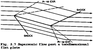
We can now look at some flow patterns which are typical for supersonic Mach numbers, again with a view to finding some that are suitable for engineering applications. An instructive example is a twodimensional flat plate which is placed at a small angle of incidence a to an inviscid supersonic stream. Although we shall find later that we cannot see any worthwhile aircraft applications for this type of flow, it can help to explain some properties of supersonic flows, as a counterpart to the corresponding incompressible flow in Fig. 3.3. The supersonic flow is shown in Fig. 3.7. Since the leading edge cannot have an upstream influence, the attachment line lies along the edge, so that there is no flow around the leading edge and no need to round it off, as in subsonic flow. But, as a consequence, a suction force at the leading edge, as given by (3.30), does not occur, and this is the origin of the wave – drag due to lift. There is an oblique shockwave on the lower surface and a Prandtl-Meyer expansion fan on the upper surface, both of such strengths that the flow is deflected through the angle a. Downstream of the leading edge, flow direction and pressure remain constant until the trailing edge is reached. There, the pressure is equalised by means of a shockwave on the upper surface and a Prandtl-Meyer expansion on the lower surface, turning the flow back into the initial direction. We note that the Kutta condition of smooth outflow is not fulfilled. But there is no need for this since a viscous flow could, in principle, negotiate the flow deflection. Clearly, the pressure is higher than the ambient pressure along the lower surface and lower along the upper surface. Conceptually, this is a very obvious way of generating a lift force. The equivalent of the lift is found in the downward momentum of the air which has been subjected to the waves. In a linearised treatment, first carried out by J Ackeret (1925), the pressure coefficient is given by
and hence the lift and drag coefficients by
so that the lift-to-drag ratio is
L/D = cot a. (3.49)
This drag is all wavedrag due to lift, as defined above (but note that this twodimensional flow leads to a value of Ky which is not constant (= J тг/В) ). In the absence of a suction force at the leading edge, the resultant force is normal to the plate and not normal to the flow direction, as in the corres
It is clear, even from these specific results, that the supersonic flow past an unswept wing differs fundamentally from the classical subsonic aerofoil flow, so that an aircraft designed on these two different principles to fly at both subsonic and supersonic speeds would experience radical changes in its characteristics during flight. Although such aircraft have been built, they do not conform to our general design principles and we search, therefore, for another type of flow which suits our purpose better.
We shall see later in Chapter 8 that typical aircraft to fly at supersonic and hypersonic speeds should be threedimensional lifting bodies and essentially different in shape from classical aircraft with wings of considerable lateral
extent. A simple method for constructing such lifting bodies has been suggested by T R Nonweiler (1963). Parts of known flowfields are used, and we consider next an example which will lead to the third basic type of flow to be used in aircraft design (for a general survey of these matters, see e. g.
D KUchemann (1965)).
We begin with the supersonic inviscid flow past a twodimensional wedge, the top of which is parallel to the mainstream, as indicated in Fig. 3.8. This body causes only one disturbance, a plane shockwave which is attached to the
|
Fig. 3.8 Supersonic flow past a twodimensional wedge |
leading edge. The flow is like that over the front part of the lower surface of the flat plate in Fig. 3.7. The pressure behind the shockwave is constant and exact values are known, depending on the deflection angle and the Mach number. The design principle is now to form solid surfaces from the streamlines of the flow. If such surfaces extend up to the shockwave, the overall flow is not changed. We then have a threedimensional lifting body with an open base, which has the undisturbed pressure over its top surface and a uniform pressure over its lower compression surface, which is higher than the ambient pressure.
A piece of the initial plane shockwave is contained between the leading edges. This feature imposes the condition that the leading edges are aerodynamically supersonic, that is, the velocity component normal to the leading edge must be greater than the velocity of sound.
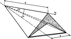
Aerodynamically, the simplest of these bodies is one where the compression surface is formed by two plane surfaces intersecting at a ridge line which lies in the lower surface of the initial twodimensional wedge. With the upper ridge line lying in the mainstream direction, this body has a cross-section like an inverted V, as indicated in Fig. 3.9. These wings are sometimes called
|
Fig. 3.9 Caret wing supporting and containing a plane shockwave. After Nonweiler (1963) |
accpet wings. They have a delta planform.
Nonweiler’s concept of starting with a known shock shape and determining a threedimensional body which supports and contains it between its leading edges is not restricted to this simple kind of conical body with flat surfaces and a single plane shock. For instance, L H Townend (1963) has suggested starting
|
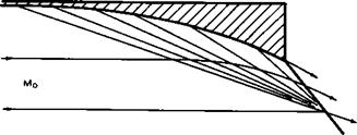
Fig. 3.10 Curved wedge surface with centred compression |
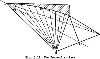
from a basic flow which incorporates an isentropia compression through an infinite number of infinitely weak shockwaves coming from a twodimensional curved wall. A simple flow of this kind is obtained by reversing the Prandtl – Meyer expansion flow. The resulting flow past such a curved wedge is sketched in Fig. 3.10. From this, a compression surface with straight leading edges
|
|
can be constructed, taking the curved shape of the initial wedge as the lower ridge line. As shown in Fig. 3.11, the two halves are ruled surfaces, generated by straight lines radiating from the wing tips. A range of designs is possible between the isentropic and the single-shock compressions. An extension to more general curved surface shapes has been made by J G Jones et at.
(1966) , who start with the flowfield of a right circular cone at zero angle of incidence and use part of the initial conical shockwave. The simplest shape of this kind is the half-cone underneath a thin flat delta wing, with the conical shockwave attached to the leading edges, as proposed by A J Eggers (I960)). There is thus a great variety of shapes that can be designed to generate lift by means of shockwaves. In every case, the inviscid flow is known exactly.
For obvious reasons, a descriptive generic term for lifting bodies of this
kind is waverider. They exhibit the third basic type of flow for generating lift forces. These matters will be discussed in more detail in Section 8.2.
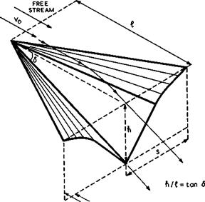
A further generalisation can be made by designing the top surface of such lifting bodies in a similar way from known expanding flowfields. J W Flower (1963) has constructed a simple shape from the twodimensional Prandtl-Meyer expansion where the flow is deflected through an angle 6. Sections of this flow may be put together as indicated in Fig. 3.12 such that the leading edges of the threedimensional expansion surface lie along the first characteristic surface and issue from a chosen apex. The surface downstream of the leading edges is
|
PLANE CONTAINING TRAILING EDGE Fig. 3.12 Flower’s expansion surface |
formed by the streamlines of the twodimensional flow which pass through the leading edges; hence the surface is curved first and then plane. The keel of the surface is straight and inclined downward from the mainstream direction.
Lastly, non-lifting volume-producing bodies can also be designed according to these principles. This has been suggested by G I Maikapar (1959) who obtained symmetrical bodies with star-shaped cross-sections and plane shockwaves contained between the edges and joining the tips of the stars.
Although the effects of viscosity pose many problems in the design of wave – rider aircraft, there is, in general, no particular difficulty in fitting a viscous layer into the inviscid design flows without upsetting their essential features. There are displacement effects, especially near the leading edges, but these need not change the general flow pattern. Exceptions to this are compression surfaces where the pressure is not uniform, as in the flow past a Townend surface. There, the boundary layer develops spanwise crossflow velocities even though the external streamlines are straight in planview.
Design problems arise mainly in fitting compression and expansion surfaces together and also in the shaping of the backend. These problems are closely related to detailed aircraft requirements and also to the way in which propulsive forces are incorporated into the design. These matters will be discussed later in their proper contexts in Chapter 8. The same applies to the whole complex of problems arising in off-design conditions, which are of considerable practical importance.
In general terms, waveriders are a type of aircraft where the means for providing volume3 lift, and propulsion are so closely integrated that their effects cannot readily be separated from one another. For example, it is impossible to say whether the wavedrag of a caret wing is caused by its volume or by its lift. For the same reason, an "aerofoil theory" like that for the classical aircraft described in Section 3.2 cannot readily be derived. In principle, (3.7) and (3.8) for the lift and drag forces still hold, but it is no longer possible to simplify them on the assumption that the perturbations are small. Also, the farfield of the lifting body of finite span and length would have to be determined, including all the essential non-linear effects. This has not yet been done; it is probably a more difficult undertaking than the direct determination of the nearfield. Thus it would appear that the farfield approach is not attractive in this case, and that the forces and moments acting on such a body can be obtained more conveniently from the pressures over the body surface. The discussion of these matters in Chapter 8 will follow these lines.


