Swept wings in supersonic flow
4.9 Much of what has been said above about the aerodynamics of swept wings in transonic flows applies again when the mainstream Mach number is supersonic. After all, we have already seen from Figs.
4.8 and 4.9 that swept wings can, in principle, be designed to have basically the same type of flow up to Mach numbers of about 2 if the angle of sweep is suitably increased. These matters have been discussed in review papers by J A Bagley (1961) and by R C Lock & J Bridgewater (1967).
We want to exclude here lifting bodies which generate strong shockwaves (these will be discussed in Chapter 8); so perturbations may be assumed to be small
and the extensive body of linearised theories for supersonic flows applied. These theories are described in many textbooks already mentioned (see also E Carafoli (1969)). Numerical methods for calculating the loading over swept wings with good accuracy are also available (see e. g. G M Roper (1966), A Roberts (1968), M F&iain (1970)), and methods which make use of an electrical analogy have been developed (see e. g. M Enselme (1970)). Therefore, we can concentrate here more on the physical design aspects.
One of the striking features of the supersonic flow past wings is the existence of wavedrags, both due to volume and due to lift, as explained in Section
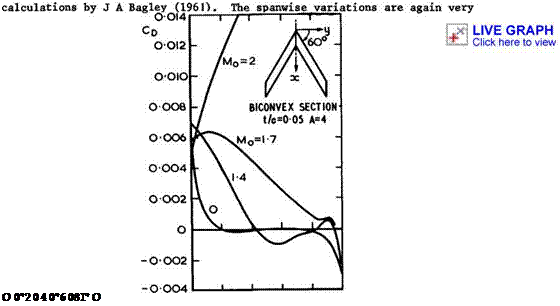
3.4. This split into two contributions is convenient; it is justified within linearised theory and usually helps in evaluating experimental results. The two wavedrags are, in general, assumed to be additive. The wavedrag due to thickness is clearly illustrated by the example in Fig. 4.74, which shows the spanwise distribution of the pressure drag of a thick non-lifting wing, from
 |
У/s
Fig. 4.74 Spanwise distribution of pressure drag on a sweptback wing large. The results for various mainstream Mach numbers invite the interpretation that the drag due to the centre effect grows and spreads further out along the span as the Hach number increases, and that the thrust due to the tip effect tends to disappear г hence the existence of an overall drag from Mq * Г onwards (in linearised theory).
The overall drag can now no longer be approximated by (3.42) but must be replaced by (3.46) which includes wavedrag terms. This implies in turn that the performance analysis given in Sections 4.1 and 4.2 does not strictly apply to supersonic flight (except the results in Fig. 4.9) and that the basic geometric parameters which resulted from this must be revised.
To describe the overall geometry of an aircraft, we need, apart from the wing area S, three further parameters to account for the overall length І, the
overall span 2s, and the overall volume Vol of the wing or body, whatever its detailed shape. Following Collingbourne (1959, unpublished), we use a convenient set
|
s/Z |
, the semi span-to-length ratio, |
|
|
p = S/2sZ |
, a planform shape parameter, |
(4.138) |
|
T – Vol/S3/2 |
, a volume parameter. |
(4.139) |
Note that the aspect ratio A = 2(s/Z)/p is not then an independent parameter. Primarily, these parameters define the size of a box with the sides Z and 2s, into which the aircraft can be fitted, and describe how much of the plan area of the box is taken up by the aircraft. (Classical aircraft with unswept wings occupy roughly a square box since the length of the fuselage is about the same as the span of the wing). The general drag relation (3.46) can now be rewritten in terms of these parameters:
°D “ CDF ♦TT"W,)| +^ГСЬІ? гК + V*2^*)2] * <4-U0>
2 2
6 = Mq – 1 . We realise at once that now a balance must be found between
ovevalt span and length of the aircraft, for a given wing area, because the drag tends to be very large when the span is too small (third term in (4.140)) and again when the length is too small (second and fourth term in (4.140)). There must be a value of s/Z for given p, or of 6s/Z for given Mq, at which Cjj is smallest. Comparing (4.140) with the relation (3.42) for subsonic flows, where the drag is the lower the larger the span, we now have s/Z
|
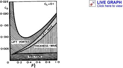
Fig. 4.75 Typical contributions to the overall drag coefficient at Mq = 2 |
occurring both in the denominator (of the vortex drag term) and in the numerators (of the wavedrag terms). We may state quite generally that it will pay to use as low a value of p as possible and that the best box size will then follow. A typical example which demonstrates the magnitude of the various drag terms is shown in Fig. 4.75. (In this figure, fairly realistic values have been chosen for the numerical values of the constants involved, representing a relatively large airliner; see D KUchemann (I960)). The main conclusion to be drawn from these results is that the lowest drag for a given lift, or the thickest wings, are obtained when the value of 6s/Z is well below
unity. For flight at supersonic speeds, volume and lift should be distributed over a length which increases with increasing Mach number, that is to say, the box size should get more and more slender and narrow. As a rough guide,
s/г lies between 0.3 and 0.4 and 3s/А is about 0.2 at Mq = 1.2 ;
sh lies between 0.15 and 0.25 and 3s/£ is about 0.35 at Mq = 2 ;
s/г. lies between 0.05 and 0.15 and 3s/& is about 0.5 at Mq = 5 .
This means that the aircraft, whatever its detailed shape, should always tie weVL within the Maeh acme from its nose, if it is to be of a type that obeys the present set of (small-perturbation) aerodynamics.
This is a result of considerable generality, and it has been found (see D Ku- chemann (I960)) that the best box size is not very sensitive to the actual values of the parameters and drag factors, and that even drastic changes in the latter make little difference. Smaller values of the planform shape parameter p correspond to slightly wider boxes; better values (i. e. smaller values) of Kq allow wider boxes; as do better values of % and worse values of Ky. Generally, worse (i. e. higher) values of Kq, Ky, and Ky give lower values • of the lift-to-drag ratio for a given value of the volume coefficient т or restrict t to lower values for given L/D; whereas lower values of p improve matters. It also matters how large the wetted area is in relation to the plan area as this affects the value of Cpp. The general result is not substantially changed if configurations are considered where the length of the volume differs from that of the lifting surface. The extreme case of this kind is evidently obtained when only the last two terms in (4.140) are assumed to depend on s/г or, what is equivalent, when т is assumed to be zero. In that case, we have 3CD/3(sM) = 0, i. e. the drag is lowest and L/D highest, when
Ss/г = д/ Ky/2Ky, (4.141)
so that 3s/г ^ 0.707 since in most cases Ky > K^ . A small but non-zero thickness will bring the value of 3s/г for the best L/D below 0.707.
A great deal of work has been done on the question of how to determine the values of the drag factors and how to find optimum values under certain conditions, within the assumptions of linearised theory. We refer here to the work of R T Jones (1952) and Mac C Adams &W R Sears (1953) (see also Sections 3.4 and 6.7). The determination of the wavedrag factor Kq due to volume and the wavedrag factor Ky due to lift within linearised theory can be done in two ways, giving the same answers: by integrating the pressures over the surface of the wing; or by applying the supersonic area rule (see e. g. W D Hayes
(1947) , G N Ward (1955), H Lomax (1955)). The area rule expresses the drag of a distribution of singularities, planar in the present case, as an average of the drags of a set of lineal singularity distributions. Each lineal distribution is obtained by considering a family of parallel Mach planes (i. e. planes inclined to the mainstream at the Mach angle defined by (3.43)) and by transferring the singularities which lie in each plane to the point where it cuts the streamwise axis. For example, as far as the volume is concerned, the sections cut by a family of Mach planes are projected on to planes normal to the mainstream, and the streamwise distribution of these projected areas (called the oblique area distribution) is that of the equivalent body of revolution, whose drag can be more readily calculated. This is a more general version of the sonic area rule discussed in the previous Section. These techniques lead to general relationships between the wavedrags and the geometric parameters s/г, Зз/г, p, and t, which have been incorporated into (4.140). It must be remembered, however, that the drag factors Kq and Кц may vary with Mq for any given configuration.
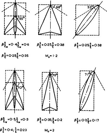
We can now deal with the question of how to fill the boxes determined above with realistic aircraft shapes which have flows that can be safely used in engineering applications. Three possible configurations are shown in Fig. 4.76:
|
Fig. 4.76 Some typical aircraft shapes for supersonic flight |
A swept wing with fuselage; a slender wing; and a slewed wing.(The term "slew" is used here to denote a rotation about the yaw axis, which transforms a basic shape into the planform under consideration. Thus the term "yaw" may be reserved for rotations of the resulting wing away from its direction of steady flight; and the term "shear" for wings obtained by shifting backwards, or forwards, sections of an unswept wing). The figure does not include other configurations which are sometimes used in aircraft and missile designs, such as unswept wings on discrete fuselages; these will not be discussed here. The figure includes slender wings for supersonic flight, which will be discussed in detail in Chapter 6. The other two wings in Fig. 4.76 have basically the classical attached aerofoil type of flow discussed in this Chapter. Fairly
realistic and conservative numerical values have been used to represent possible aircraft, and the boxes as well as the shapes inside them have been drawn to give the best value of L/D, at the flight Mach number indicated. These are the shapes to bear in mind for potentially useful applications: on the one hand for flight at low-supersonic speeds where, in principle, sonic bangs may be avoided; and on the other hand for flight at a Mach number around 2, which appears as probably the highest reasonable flight Mach number for these shapes – higher speeds would require configurations which would have to fit into exceedingly narrow boxes (see also L T Goodmanson & L В Grat – zer (1973)).
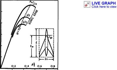
Consider now the performance of the swept configurations in Fig. 4.76 in some more detail. Fig. 4.77 shows some maximum values of the lift-to-drag ratio calculated for wing-fuselage combinations. This is the one case where it is
![]()
![]()
![]()
![]()
![]()
 12
12
(a8
6
reasonable to make a distinction between the length Z of the volume-providing body or fuselage and the lifting length of the wing (see also Section 6.2).
The planform shape parameter p^ now refers to the wing alone within its own surrounding box, and the results show how profitable it is to find shapes with small values of p^ . The drag factors chosmfor the cases in Fig. 4.77 are:
Kq * 1 , because one would attempt to approach this value of the best body of revolution for the given length and overall volume; and Ky = – 1 , because
one would hope to find wing shapes with nearly elliptic loading, both spanwise and lengthwise. The results confirm that the most efficient configurations lie well within the Mach cone from the nose and that the wing itself is also nominally subsonic: there would seem to be no point in going to a sonic leading edge. (The actual performance would then be expected to be worse than shown in Fig. 4.77 because the drag factors would be higher than assumed). We may, therefore, conclude that the main trends established in Section 4.2 for a family of swept wings still hold at supersonic speeds and that the existence of wavedrags does not invalidate them. The aerodynamic problems are thus much the same as those discussed above, especially those associated with mixed transonic flows.
If cruise performances like those in Fig. 4.77 could be achieved in practice, swept wing-fuselage combinations would be perfectly suitable for supersonic flight over medium and long ranges (see Section 4.2). The real design problems lie elsewhere, namely, at low speeds, where it is very difficult to keep the flow attached over such a highly-swept leading edge, as explained in Section 2.4 in connection with Fig. 2.5. Obviously, separation leading to a type of flow like that in Fig. 4.37 should be avoided. So far, these low-speed problems of highly-swept wings have not been solved satisfactorily.
We may mention in this context that cranked wings with planforms shaped like a W or an M have some attractions. Again in combination with a fuselage, an Mowing would fit into a slightly wider box than the corresponding swept wing, and it could have a greater span and planform area and thus could fly at lower CL-values. This might be an asset at both low and high speeds; it may be taken up by making the wing thicker and this, in turn, may lead to lower structure weights. An M-wing might be lighter than a swept wing, anyway, because its requirements for bending and torsional strengths are less severe. On the other hand, the larger number of kinks and their associated kink effects make the aerodynamic design much more difficult, and these design problems have not yet been overcome. Nevertheless, M-wings remain a serious contender for possible future aircraft.
As soon as Betz proposed the application of sweep in 1940, it became clear that the aerodynamic problems concerned not only the cruise design but also the increasingly unsatisfactory characteristics at low speeds. Thus the concept of ‘Oariable sweep almost suggested itself as a possible remedy, for the purposes explained in Section 4.2. So E von Holst (1942, unpublished) suggested the slewed wing as the simplest way of achieving variable sweep (on "air bearings", without hinges) and built and flew a number of models to demonstrate their generally satisfactory stability and flying characteristics. These models included not only asymmetrical configurations, without and with a fuse-
|
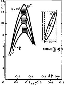
Fig. 4.78 Lift-to-drag ratios of slewed wings at Mq ■ 2 |
LIVE GRAPH
Click here to view
lage, but also symmetrical arrangements with scissors-like biplanes. Circumstances prevented the conqiletion of an actual aircraft with a slewed wing. In the meantime, the slewed wing has been "invented" again by J P Campbell & H M Drake (1947), who made experiments to test the flight stability, and by R T Jones (1958) who provided some of the theoretical background for the design for supersonic speeds and also demonstrated models in flight. J H В Smith
(1961) extended the theory to include wavedrag due to volume and calculated the lift-to-drag ratios of optimised wings. We show in Fig.4.78 some typical results for elliptic planforms, that is, wings which provide volume and lift simultaneously. We find that the general level of L/D is about the same as for swept wing-fuselage combinations; this would allow such aircraft to fly over medium and long ranges. We also find that the angle of sweep should lie within a fairly narrow band for best efficiency. The lift-to-drag ratio falls steeply if the angle of sweep is too high (<p = 90° where the curves end on the lefthand side), and again if the angle of sweep is too low (the main axis of the wing lies along the Mach line and is sonic where the curves end on the righthand side). So these slewed wings confirm the earlier statement that wings should lie well within the Mach cone. This implies, in turn, that slewed wings should be designed to have the same type of attached streamline flow as swept wings.
The examples in Fig. 4.78 assume that the slewed wing would be an atbHng aircraft with sufficient volume inside the wing to accommodate the payload. Such layouts have been considered further by G H Lee (1960) and (1961) who concluded that the payload of such an aircraft may, in fact, be significantly better than what is implied in the results given here. R T Jones (1972) and (1974) and R T Jones & J W Nisbet (1974) have reached similar conclusions for layouts which include a fuselage. Jones argues that the antisymmetric arrangement of a slewed wing and a fuselage is potentially more efficient than the mirror – symmetric swept wing-fuselage combination and suggests a possible application to transport aircraft operating up to low-supersonic speeds. Jones estimates the drag to be lower than that used in Fig. 4*9 for symmetrical wings, i. e.
|
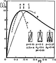
Fig. 4.79 Lift-to-drag ratios of three configurations at Mq – 2 |
LIVE GRAPH
Click here to view
(L/D)m ■ 17.7 near Mq = 1 for the slewed wing instead of 15 for the swept wing. Again, slewed wings remain a serious contender for possible future aircraft.
We summarise this discussion by plotting the maximum values of the lift-to – drag ratio for the three candidate configurations in Fig. 4.79. Within this first-order accuracy, the best aerodynamic efficiency at cruise can be made to be the same for all three. Only a much more detailed design study, together with considerations of off-design conditions, could show genuine differences, if any. As far as the swept wings are concerned, we shall see in Chapter 5 in more detail that some of the design features needed for efficient cruise do not, in fact, suit the low-speed characteristics; and that, for the variable-sweep schemes, it must be borne in mind that sweep is the only shape parameter which is then changed whereas many others cannot readily be undone. Thus, in the end, swept wings may be most suitable for flight at high-subsonic and low-supersonic speeds, and slender wings may offer the most natural solution for flight at about twice the speed of sound. Slender wings will be discussed further in Chapter 6.
![]()


