Some propulsion problems
To follow up the general discussion in sections 3.6 and 3.7, we now turn to some problems which are associated with the propulsion system of classical and swept aircraft, confining ourselves in the main to propulsion by turbojet or turbofan engines because we have seen (in section 4.2) that these types of engine go well together with this type of aircraft. The aerodynamics of propulsion is a wide field (see e. g.
D Kilchemann and J Weber (1953)), and we want to take up here only a few particular topics of engine-airframe interference, which are thought to be especially relevant to aircraft design:
air intakes; nozzle and jet flows; afterbody and base flows; nacelle installations; noise shielding.
The discussion here supplements and follows on from what has already been said in sections 3.5 to 3.7 on the means of generating propulsive forces and in section 5.2 (Fig. 5.5) on possible ways of generating lift and thrust forces together. Here, we are especially interested in the question of how the particular flow or design element is affected by the aircraft environment in which it operates, when there are strong interference effects between the engine flowfield and the airframe flowfield. Detailed reviews of these problems may be found in A Ferri (1972) and (1975) and in the papers in AGARD Conference Proceedings CP-150 (1974).
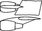
Consider what happens when a subsonic air intake, as in Fig. 3.24(a), is put near the wall of another part of the aircraft, e. g. of the fuselage or the wing. In a very simple way, such an intake could be designed by starting with a complete intake without a wall, which is elongated or nearly twodimensional. The plane of symmetry could then be made into a wall, as sketched in Fig. 5.77, and a forward-facing ‘pitot’ intake on a wall obtained with the same flow pattern as before, were it not for viscous effects: a boundary layer will develop along the approach wall, which may even separate in the strongly – retarded flow, as indicated in Fig. 5.77. This leads to a reduction of the
|
Fig. 5.77 Air intake with a plate in the plane of symmetry (full lines) and without a plate (dashed lines) |
mass flow into the intake, and also reduces the efficiency of the engine flow cycle as a result of a loss in mean total head and of non-uniformities of the velocity distribution ahead of the engine face (see section 3.7). Such a flow must be avoided by design: a boundary-layer ’bleed,’, that is a suction slot, may be incorporated in a suitable place; or an intake of finite width may be lifted off the wall to a distance of about one boundary-layer thickness so that the approaching boundary layer can escape sideways around a suitably – shaped fairing between intake and wall.
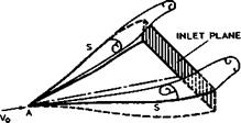
Another way to divert the approach boundary layer from intakes actually submerged in a wall leads to the NACA intake, as described and tested by G W Frick et al (1945) and E A Mossman and L M Randall (1948). The sketch in Fig. 5.78 indicates that air enters a three-sided diffuser upstream of the
|
Fig. 5.78 NACA intake submerged in a wall |
inlet proper; the upper side of the diffuser is open, and the bottom wall is a straight ramp sloped by about 7°. From the apex at A, the side walls diverge and their sharp top edges S can be expected to act as separation lines, from which near-conical vortex sheets with rolled-up cores are shed. These will sweep some of the boundary-layer material sideways in a flow pattern that is rather similar to that generated by swept steps, as sketched in Fig. 5.26. As is often found when particular schemes have succeeded in reducing approach losses by diverting the boundary layer, the price to be paid for that is an increase in external drag, in the present case as a consequence of the sweeping vortices left behind in the external flow. A theoretical study of submerged air intakes has been made by A H Sacks & J R Spreiter (1951). Experimental data has been correlated more recently by R M McCreath & A J Ward-Smith
(1967) , and a prediction method, based on a simplified model of the flow, has been provided by A J Ward-Smith (1973).
We cannot say, however, that the design aim should always be to divert the boundary layers away from the engine intake: the opposite may also be a profitable design aim, where the boundary layer is deliberately ingested into the engine. We saw in section 3.7 that inflow losses reduce both thrust and propulsive efficiency; but if boundary-layer air is ingested, the thrust required is also reduced so that a net saving of fuel consumption may be achieved. Ideally, if the wake of the whole aircraft could be diverted into the engine, it would only be necessary for the engine to restore the momentum of the air in the wake to that of the free stream, so that no net thrust would be required. In a more practical case, the ingestion of part of the boundary layer would allow a reduction of the engine thrust by an amount equal to the drag which is represented by the loss of momentum in that mass of air. If an aircraft does not ingest boundary-layer air, then relative to the ground this air is being accelerated forwards and a corresponding amount of air has to be accelerated backwards by the engine. The alternative of returning the boundary-layer air to rest takes less power from the engine since it is itself moving forwards. Thus, in principle, this could be a more efficient way of propelling an aircraft than that implied in Cayley’s concept where thrust is generated separately to balance the drag. The savings in fuel consumption from boundary-layer ingestion, in some circumstances, could be substantial. These promising possibilities have not yet been practically exploited, but they may receive more attention if the problems of fuel shortages and increasing costs become more serious (see e. g. J В Edwards et al (1973)). The aerodynamic problems involved have been discussed by D. KUchemann & J Weber (1953, section 9.7) and in a classic paper by J В Edwards (1961). The engine design ‘would also have to be adapted for the purpose, and suitable structural concepts would be needed to avoid weight penalties from such a buried engine installation.
At supersonic flight speeds, part of the compression in the air entering an intake is achieved through a shockwave or a system of shockwaves. External compressions (upstream of the inlet plane) may range from flows with a single, nearly normal, shock standing off a forward-facing pitot intake to flows with an infinite number of weak shocks, as discussed in section 3.7 (Fig. 3.26).
A simple flow between these extremes is that into an annular intake with conical centre body, as sketched in Fig. 5.79. As in the case of Fig. 5.77, parts of the flowfield may also be used by making a streamsurface into a solid wall. For example, a halfcone on a plane wall gives the same flow pattern, except for viscous effects. We can also readily think of the corresponding twodimensional flow, with a wedge acting as a compression surface, and again parts of such a flow may be used if streamwise sideplates are provided.
|
Fig. 5.79 Air intake with conical centrebody at supersonic speed, running full |
The flow in Fig. 5.79 is that at the design condition where the intake is running full, i. e. the two shockwaves intersect at the rim of the intake lip and there is only one shockwave in the air passing the outer surface of the intake. This flow implies that there is a pressure drag acting on the external surface of the intake (i. e. there is no suction force as in subsonic flows, according to (3.84)). The main design problem in any supersonic air intake of this kind is then to strike a balance between this external wave – drag and the pressure recovery in the air entering the inlet, which will be below that of an isentropic compression because of shockwave and viscous energy losses (see e. g. EL Goldsmith & C F Griggs (1959), and also section 3.7). Strictly, the effect of the pressure recovery on thrust and fuel consumption of the engine must be known to find the right balance between thrust and drag forces.
The flow is much more complicated in off-design conditions and when the flow – field of the airframe affects the air intake so that it cannot be designed in isolation. At Mach numbers and mass flows below the design values, the intake spills, i. e. the first shockwave (in Fig. 5.79) steepens and the second moves forward so that the two shockwaves intersect at some point upstream of the intake lip, generating a vortex sheet. This flow, which includes interactions between shockwaves and boundary layers, is basically the same as the flow element discussed in connection with Figs. 2.11 and 4.64 (see e. g. I McGregor
(1972) ). Since the separation lines and shock positions are not firmly fixed, the flow into the intake may be unsteady and lead to what is called intake buzz. In addition, the design of the forebody of the fuselage or of the wing may play an important role in inlet performance and inlet-engine compatibility. Side-mounted air intakes are quite sensitive to forebody camber and to the shape of the underside of the fuselage. In some installations, the wing may be used to ‘shield’ the intake so as to reduce local angles of attack at the inlet during manoeuvering flight; such designs are quite sensitive to wing position. A discussion of these problems and of the various engine parameters that must be taken into account in the design may be found in P P Antonatos et al (1972). How these problems can be tackled experimentally has been discussed by E C Carter (1972).
It is in the nature of these interfering flows that several successive oblique shockwaves may occur and interact with the turbulent boundary layer. A computation procedure for predicting such flows, including bleeds with small mass flow at the second interaction, has been developed by С C Sun & M E Childs (1974).
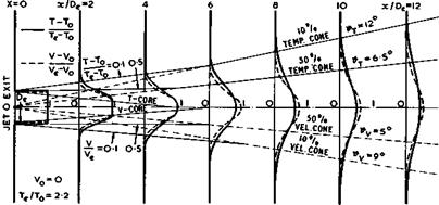
Next, we remind ourselves of some properties of nozzle and jet flows, first in the absence of interference from other parts of the aircraft. The shape of the nozzle may be circular or annular, and a variety of conditions may prevail at its exit: the emerging jet may be subsonic or supersonic and the mean exit pressure may be smaller or greater than the ambient pressure outside it. Consider first the simple case of a subsonic jet emerging with velocity Ve and temperature Te from a circular nozzle into still air. The experimental results in Fig. 5.80 give typical time-average velocity and temperature
|
Fig. 5.80 Velocity and temperature distributions in a round jet in still air. After 0 Fabst (1944) |
profiles and illustrate the ‘turbulent mixing process’ which leads to a gradual spreading of both momentum and temperature. Simplifying the geometry somewhat, we may describe the jet as having a velocity core, with exit velocity Ve, which narrows with distance from the exit and then fades out; and a temperature core which is slightly shorter. Further downstream, the velocity reaches certain fractions of Ve roughly along conical surfaces. Corresponding temperature cones are slightly wider. When the jet is discharged into streaming air, the spreading is stretched out in the streamwise direction. A first approximation to the spreading can be obtained by superposing the external flow with velocity Vq on the jet flow into still air (see e. g. D KUchemann and J Weber (1953), Chapter 10).
Interesting phenomena occur when the nozzle exit is not circular but elongated into an oval shape. In the first place, the jet changes its shape: with increasing distance from the nozzle, the lateral (wider) dimension is reduced (see e. g. H Viets (1972)). In the second place, if the nozzle is designed to produce a parallel outflow, the velocity direction in the external stream around the threedimensional afterbody at the rim of the nozzle is likely to differ from the jet direction. This means that streamwise trailing vorticity is shed from the nozzle, which may roll up into a pair of counter-rotating vortex cores on each side of the nozzle, as has been observed by A G Kurn
(1974) . The streamwise vorticity component will be much stronger if the jet is inclined to the mainstream. The jet is then bent back towards the mainstream direction and its cross-sectional shape deformed at the same time. For instance, an initially round jet will become lobed and assume a bean-shaped cross section and may even split into two separate jets if the jet inclination is large enough. .
In reality, the actual jet flow is much more complicated than these simple time-average flow models suggest. They are by no means fully understood, even though they have been the subject of much research for a long time. Of more recent accounts, we mention here an approximate analysis by J A Schetz (1971), which includes effects of swirl in the jet, and measurements by 0 H Wehrmann
(1972) and by G Brown & A Roshko (1972). The latter suggest quite an orderly structure in the mixing zone along the jet core, in keeping with the arguments put forward in connection with Figs. 2.14(c) and 3.23(c).
Sonia state is reached in the exit plane when the pressure ratio in the nozzle, between pn at the beginning and pe at the exit, is
X, U89
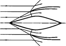
for у = 1.4, according to the Saint-Venant theorem, if the Mach number at the beginning of the nozzle is low enough to be taken as zero. For non-zero Mach numbers there, the pressure ratio must be somewhat greater than 0.528 to reach the sonic state. When a parallel supersonic jet emerges from the nozzle exit, it will subsequently undergo characteristic deformations, even in the absence of viscous effects. Two typical examples are sketched in Fig. 5.81, showing
|
|
(a) DISCHARGE PRESSURE HIGHER THAN THE EXTERNAL PRESSURE
P<|Po
I,’PoV
>. If————–
(b) DISCHARGE PRESSURE LOWER THAN THE EXTERNAL PRESSURE
Fig. 5.81 The discharge of a supersonic jet from a nozzle
the systems of compression waves (full lines) and expansion waves (broken lines) which appear when the discharge pressure pe is either higher or lower than the external pressure pq. The pattern in each case is readily understood if we remember that both kinds of waves are reflected, with a change of sign, at the jet boundary, along which the pressure must be equal to the ambient pressure.
We can now proceed to consider interference effects between jets and other parts of the aircraft. What happens in non-uniform flows with jets near lifting surfaces has already been discussed in section 5.8. But the spreading of a subsonic jet is already affected by the presence of a nearby plane wall parallel to the jet. Entrainment of air into the jet is then hindered or prevented on one side, and there is a tendency to adhesion, with the jet bending towards and then sticking to the wall. This is a desirable feature in some particular applications, such as blowing over a flap and making use of the Coanda effect (see e. g. H Riedel (1973)). But it also has undesirable consequences, such as heating, fluctuating pressures, and dynamic loads, especially when a jet impinges on a surface (see e. g. R Westley et at (1973),
D L Lansing et at (1973)). An effective way to remedy this is to provide a stream of fresh air between the jet and the wall. For example, if an engine nacelle is installed on the wall of a fuselage, the flow past a suitably – shaped fairing between nacelle and fuselage, with a sharp trailing edge, will Vent the jet sufficiently and cushion it from the wall.
There are other cases where the jet cannot be prevented from scrubbing surfaces downstream of the nozzle exit. For example, the nozzle of the cold stream of a turbofan, or fan jet, engine usually ends well upstream of the nozzle of the hot stream, the fairing over the fan being significantly shorter than the whole engine. The flow is particularly complex when the fan jet is supersonic but embedded in a subsonic flowfield. The pressure distribution along the afterbody is then determined by the pattern of expansion and compression waves in the fan jet, and poor afterbody shapes may reduce the overall thrust by 3 to 4%. An approximate method for calculating such flows, supported by experimental results, has been provided by C Young (1972).
In all the nozzle and jet flows discussed so far, we have tacitly assumed that the nozzle ends in a sharp edge. This need not be so in many practical cases, where blunt rearward-facing bases near the end of a nozzle are quite common. Therefore, we concern ourselves next with base flows.
The flow over bases and over rearward-facing steps has been studied extensively at low speeds as well as at transonic and supersonic speeds (see e. g.
J F Nash et at (1963), H H Korst (1956), J Reid & R C Hastings (1959)),
J C Cooke (1963), R C Hastings (1963), J Gaviglio et at (1972), M Tanner
(1973) ). A simple model we can have in mind is a flow where a separation line is fixed along the outer rim of the base at all speeds, and where the base is a plane surface normal to the undisturbed stream. The flow is simplest when the body upstream of the base is a cylinder along the mainstream direction.
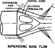
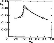
The separation surface is a bubble, as discussed in section 2.4, which closes somewhere downstream of the base. On time-average, no air flows through the dividing streamsurface of the bubble surface but there is nevertheless some mixing in the shear-flow region between the external stream and the air inside the bubble, which slowly revolves in two weak eddies. More intense turbulent mixing occurs in the region where the two streams from either side meet to form one rather thick Wake. This goes together with a pressure rise so that, since the pressure in the wake must be near that in the mainstream, the pressure along the bubble surface and inside it, where it does not vary much, must be below that value. This implies that the pressure over the base area is also below the mainstream value and that there is a drag force acting on the base, at all speeds. At subsonic speeds, a low pressure over the front part is a general feature of any bubble. At supersonic speeds, the external stream must have an expansion fan near the rim of the base and a shockwave system where the bubble closes, as sketched in Fig. 5.82. The edge of the viscous region is indicated there by dashed lines. Values of the base drag coefficient are also given in Fig. 5.82, from measurements by A G Burn (1963) for transonic speeds and by A F Bromm ARM O’Donnell (1954) for supersonic speeds. The base drag coefficient has a pronounced maximum near Mq = 1 .
LIVE GRAPH
Click here to view
|
EDGE OF
|
|
Fig. 5.82 Base flow and base drag of an axisyrametric cylinder |
To explain these features in detail and to predict the base drag under any given conditions is still somewhat uncertain. Many parameters matter in this type of flow, such as the thickness and state of the boundary layer when it reaches the rim of the base. Also, a high drag appears to go together with a high degree of unsteadiness in the flow. This may be reduced to some extent by putting a solid ’splitter plate1 along the plane of symmetry in a twodimensional flow. Before we give some examples, we consider a particular and instructive way of reducing, in principle, the base drag to zero: base burning.
Flows with heat addition have already been discussed in section 3.6. In the present case, we want to retain the flow separation from the base in the form of a bubble and add heat to the surrounding flow, no net heat being supplied to the recirculating flow inside the bubble. If the heat supply is adequate and gets convected downstream from the rim of the base onwards, the formerly expanding flow may undergo a sufficient thermal expansion to convert it into one at constant pressure: it is by this means that the base drag is reduced or eliminated. This type of flow was first proposed by J Reid & D KUchemann
(1960) and its existence was then successfully demonstrated in an experiment by L H Townend (1962) who found that combustion was stable in a supersonic stream, leading to an approximately cylindrical flame, when hydrogen was ejected through a slot around the rim of the base. G Winterfeld (1967) confirmed that the same effect existed also at transonic speeds and that fuels other than hydrogen may be used. Similar confirmatory results were obtained by M Elliott (1970, unpublished HSA Reports). The main aerodynamic features
of this flow were clarified by. theoretical work of E G Broadbent (1970) and
(1973) , who applied his method for obtaining exact numerical solutions for heated flows to this case (E G Broadbent (1971); see also F BartlmS. (1970)). Results of one such calculation for sonic mainstream Mach number are shown in Fig. 5.83, where a typical boundary-layer profile (chosen as parabolic for
 LIVE GRAPH

Click here to view
illustrative purposes) was allotted to the upstream velocity distribution, although viscous effects were otherwise neglected. The lower part of Fig.
5.83 shows the streamline pattern typical for this flow, with the considerable widening between them where heat is added. Isothermal contours are also plotted and give an idea of the heat addition needed. Not shown, because it is too thin, is a very narrow region of high temperature just downstream of separation. This can serve the important purpose of igniting the new combustible mixture as it leaves the base and meets the hot reacting gas in the recirculating flow, thus providing the mechanism for a stable flame. But for a complete understanding of base burning, these results must be matched with chemical kinetics and mixing theory. For this purpose, a number of adjustable parameters are needed and are available in BroadbentTs theory. The upper part of Fig. 5.83 shows the pressure distribution along the dividing streamsurface and demonstrates that the interaction takes place at nearly constant pressure. It is illuminating to compare this pressure distribution with that measured in a cold base flow by J Reid & R C Hastings (1961). The contrast is striking: it is due in part to the smaller depth of curved flow and to the much lower dynamic pressures that occur with base burning because of the much lower density at the same flow speed. Also, because of the much lower pressure gradients, the recirculating flow inside the bubble must be at a much lower Mach number with heat addition than without. From a practical point of view, there are two strong arguments in favour of base burning, as opposed to installing an engine with higher thrust to overcome the base drag or to using an engine with reheat; in its simplest form, base burning involves hardly any structure-weight penalty, and it can be switched on and off as required. Thus additional thrust, or reduced drag, can be obtained for short periods when it is most needed. However, the scheme has not so far been applied in practice.
Consider now the flow of a jet out of a nozzle which is surrounded by a base and installed in an afterbody that is not cylindrical but boat-tailed,
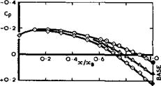
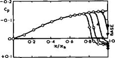
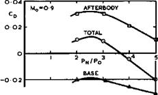
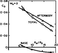
i. e. tapered down. We illustrate these flows at a high-subsonic Mach number and a supersonic Mach number, together with pressure distributions and drag values in Figs. 5.84, 5.85, and 5.86, from measurements by J Reid (1968) and (1971) (see also J Reid et at (1974)). For some aircraft, it is usual
|
|
|
|
|
O NO JET V PN /Р0-6 ЛЮ 0 14 ❖ 10 |
|
Fig. 5.85 Afterbody and base pressures at * 2. After J Reid (1971) |
practice, for simplicity and lightness, to have a plain convergent nozzle with a variable throat area, which is relatively small at subsonic cruising flight and which is increased for acceleration and for supersonic flight when reheat is applied. Such configurations necessarily leave cavity bases of variable sizes, and an important design problem is to choose the final slope of the afterbody, or the boat-tail angle, and the base areas to give low drag over
LIVE GRAPH
Click here to view
|
|
|
Fig. 5.86 Drag values on nozzles as in Figs. 5.84 and 5.85 after J Reid (1971) |
the range of flight speeds. The Jet pressure ratio pe/po an<* temperature are the main parameters for a given geometry.
Reid’s results show that the jet expands as it emerges from the sonic throat.
In the subsonic flow, separation is fixed along the two rims of the annular base and the flow remains attached to the parabolic afterbody under all conditions tested. There is a suction over most of the afterbody, but the pressure coefficient rises and is positive over the base (Fig. 5.84), in contrast to what happens in the flow past a cylindrical afterbody with a base but with no jet (Fig. 5.82). Similarly, for a cylindrical afterbody with base and jet, the total drag increases rapidly, but irregularly, with increase in jet pressure and decreases with increase in jet temperature, whereas the total drag of the boat-tailed configurations tends to decrease with increase in jet pressure (Fig. 5.86) and the jet temperature has little effect. Significant temperature effects are encountered only when the jet pressure ratio is low and when the base area is comparatively large or the boat-tail angle small.
Thus the design aims at subsonic speeds are an attached flow over shapes with a relatively small base area and a large boat-tail angle.
The flow at supersonic speeds is quite different in the cases investigated (Fig. 5.85): it separates from the afterbody before it reaches the base, even without jet flow, and the separation line S moves upstream with increase in either the jet pressure or the temperature. The resulting separation bubble goes together with a shockwave in the external flow and hence a significant pressure rise behind it. It might be said in this particular case that the interference from the jet, leading to a flow separation, is favourable because both the component drags and the total drag decrease with increasing bubble
size, caused by increasing jet pressure or temperature (Fig. 5.86). Altogether, from this evidence, the design aims at supersonic speed are a separated flow over shapes with a relatively small base area and a small boat-tail angle.
We note from these relatively simple examples of axisymmetric shapes that the combined jet and base and afterbody flows are complex and that the design aims for different speed regimes are partly in conflict. Although the main features which we have identified will remain, the flows must be expected to be much more complicated in practice, where the afterbody and the base may lack axial symmetry, where two jets may be in close proximity, and where the nozzle may be situated in the flowfield of other parts of the aircraft. Nozzle-airframe interference usually has a considerable effect on the overall performance of an aircraft, as it affects thrust and drag as well as lift and weight. Since so many aspects and parameters are involved, the design problem is very severe and requires comprehensive and accurate information for its solution (see e. g. F Aulehla & К Lotter (1972); F F Antonatos et at (1973); S F J Butler (1973)). Most of this information must be obtained experimentally, and it is in the nature of the problem that good experiments are extremely difficult to perform (see e. g. F Jaarsma (1972)).
We turn now to arrangements where the engines are installed in separately – identifiable nacelles, attached to the wing or to the fuselage. These installations would appear to conform closely to Cayley’s basic principles of ‘separate means’ and ‘no interference’, but we shall find again that there are several significant interference effects of a complex nature, which are difficult to calculate and to measure but which matter in the overall performance balance of the aircraft. To fix our ideas, we may think of a typical installation of a fan jet engine, mounted on struts, or pylons, attached to a swept wing, as sketched in Fig. 5.87. To put the discussion that follows into
|
Fig. 5.87 Installation of a fan-engine nacelle below a swept wing |
perspective, we note that the provision of the larger airstream to the fan may improve the propulsive efficiency of the engine itself by typically 25% at high-subsonic speeds, as compared with that of a straight turbojet in a smaller nacelle, but that the larger size of the engine nacelle and the increased complexity of the flow may increase the external installation drag to such an extent that the installed thrust is considerably reduced and that about half the benefit is lost again. This is why it pays so much to find out about the flows involved and to learn more about engine-airframe interference. If the trend towards engines with higher bypass ratios continues, we should begin to think of unconventional installations or consider the design of possible variable-cycle engines which can be installed more neatly.
In some fan get nacelles, the outer cowling may be relatively short so that the intake and exit flows can no longer be regarded as largely independent of each other. The flow conditions then tend to approach those of a ducted propeller, as discussed in section 3.7, and the fairing should be treated as an annular aerofoil with a circulation around it. The theory of annular aerofoils in isolation in a uniform stream is fairly well-developed. Some of their properties have already been described in section 5.7 in connection with Fig. 5.66, and we refer here to some recent methods for calculating the pressure distribution over annular aerofoils applicable to fan jet engines, by C Young (1969) and (1971) and by W Geissler (1970). But the more difficult problems arise from the interference between the fairing and what is inside it and bodies which are near it in the external flow. In all cases, there may be large interference forces between the fairing and the body, which are equal and opposite in inviscid subsonic flow but may leave significant and unwanted interference drags if they do not precisely cancel one another. In addition, a large part of the actual thrust force may act on the intake and on the nozzle of the fairing (see section 3.7 and the example in Fig. 3.28), and the losses may be considerable if the thrust forces are not realised in full.
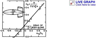
The large interference forces often arise when one of the bodies changes the streamwise velocity component at the position of the other. For example, an annular fairing may increase or decrease the velocity at a propeller or fan inside it, depending on the sign of the circulation around the fairing. It can then be shown that not only are the thrust forces on the propeller quite different from those on a propeller in an undisturbed stream, for a given power input, but that the propulsive efficiency is also changed: with a fairing which increases the velocity at the propeller, a gain in the thrust can be achieved without a loss in efficiency or, alternatively, the same total thrust can be obtained at a higher efficiency (see section 3.7 and also D KUchemann and J Weber (1953), section 6.1). Another instructive example is that where annular aerofoils with different circulations are put around a body of revolution, as indicated in Fig. 5.88. The experimental points were obtained with
|
Fig. 5.88 Measured drag of a body in the presence of annular fairings of various shapes |
a series of annular aerofoils which produced different mean values of vx/Vq inside. These velocity increments act mainly on the sinks representing the rear of the body of revolution and thus a reduction of the velocity results in an additional thrust force on the body and an increase in an additional drag. Note that the interference forces may be several times the drag of the body alone in an undisturbed stream. Yet another example demonstrating similar
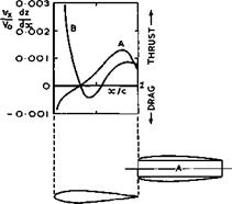
interference effects is shown in Fig. 5.89. Here, simple free-flow nacelles
 LIVE GRAPH
Click here to view
Fig. 5.89 Thrust and drag forces on wing generated by engine nacelles. After Bagley (1969)
are put near an unswept wing in different positions. The chordwise distribution of vx/Vq times the slope of the aerofoil surface gives a measure of the interference thrust and drag forces experienced by the wing, which should be counteracted by equal and opposite forces on the nacelle. In view of these flow phenomena, it is not surprising that the actual installed drag of an engine nacelle may be up to twice the drag of the nacelle by itself (see e. g. D. KUchemann and J Weber (1953), section 9.11), especially when the wing is swept and detrimental kink effects play some part. As a general design rule, underslung nacelles should be put either well upstream of the leading edge or well downstream of the trailing edge: detrimental complications must arise when sensitive flow regions – intakes and nozzles of the nacelle and leading and trailing edges of the wing – are put close to one another in the same vertical plane.
Induced cross flow velocity components may also have detrimental defects. As far as the air intake is concerned, such velocities may be caused by the wing or the fuselage; they should be taken into account in the design of the intake (see e. g. J A Bagley & H G F Purvis (1972)). As far as the wing is concerned, an engine nacelle may induce vertical velocity components which vary across the span and hence change the spanwise loading and usually cause an additional vortex drag. If the nacelle is mounted on pylons or struts, superposition and reflection effects must be taken into account, as described in section 5.6 (see e. g. C Young (1970); P Lee (1973); В C Hardy (1975)). In general, the isobar pattern over the wing is then severely disturbed, and premature local supersonic regions or flow separations may occur. In all these cases, it is difficult to find effective remedies which work not only at one specific design condition but over an adequate range of flight conditions. The general design principles discussed before apply also in these cases, the thickness variations, camber, twist, and junction shaping are the main means at the designer’s disposal. For a detailed discussion of the special problems of engine installations, we refer to summary papers by J Seddon (1952),
A В Haines (1968), J A Bagley (1969), P P Antonatos et at (1973), and W Wittmann & W Fischeder (1974).
We just mention at this point that similar problems arise with the installation of external stores, especially when these are mounted on struts below wings (see e. g. D E Hartley & A В Haines (1951), W R Chadwick (1974)
F W Martin et at (1975), and F W Martin & К В Walkley (1975)). Many of the stores have a high drag by themselves and produce a high interference drag in addition so that means for reducing the drag are well worthwhile (see e. g.
C L Bore (1974) and A В Haines (1975)).
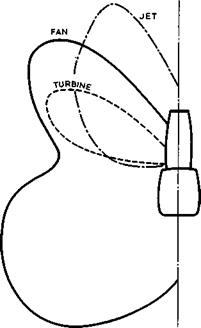
Another important aspect of the propulsive engines of aircraft is the noise they make. As an example, the noise pattern of a fan jet engine is sketched in Fig. 5.90, which shows the characteristic lobes in the contours of equal
|
Fig. 5.90 Noise pattern generated by a fan jet engine (schematic) |
intensity of the noise from the fan, the turbine, and the jet, as observed in the farfield from assumed point sources located on the axis of the engine.
Much of the sound is generated aerodynamioatty by the ’turbulence* in the boundary layers and shear layers. The flow past the other parts of the aircraft also generates noise but that from the engine usually dominates (for a study of airframe self-noise see e. g. P Fethney (1975)). Following M J Lighthill (1952) and (1954), many have investigated the mechanisms for generating sound aerodynamically and possible means for reducing it. We refer here to the summary papers by H V Fuchs & A Michalke (1973) and by D G Crighton
(1974) , by J E Ffowcs Williams and other paper published in the AGARD Conference Proceedings 131 (1974) on Noise Mechanisms. We are concerned here not
with the problem of how to make the engines themselves quieter* but with possible features of the aerodynamic design of aircraft, which may help to reduce the noise heard by people on the ground, especially in the neighbourhood of airports. The main physical phenomenon to be exploited for this purpose is noise shielding.
The principle of noise shielding is simply to use the airframe as a shield between the engine and the ground to oast a noise shadow on the ground, by mounting the sound-generating parts of the engine above some surface of the airframe. This has been proposed independently by A Betz (1966, unpublished; see F R Grosche (1968)) and by J В Edwards (1966, unpublished Handley Page Report). It has turned out to be a potentially powerful effect, and theoretical work by E G Broadbent (1975) and others has provided a sound basis for estimating it, supported by experimental evidence (see R W Jeffery &
T A Holbeche (1975); E G Broadbent (1976); D S Jones (1976)).
With a noise pattern as in Fig. 5.90, the effectiveness of noise shielding will depend on the planform of the wing. That of a slender wing is evidently well-suited for the purpose, and we shall discuss noise shielding further in the appropriate context in section 7.3. However, some degree of noise shielding can be achieved also with swept-winged aircraft, e. g. if engine nacelles are mounted over the upper surface of the wing. The first aircraft designed with this objective in mind is the VFW 614. The design of the wing, with engine nacelles mounted on pylons, then entails special problems. How these may be solved, using the design concepts and methods described above, has been reported by J Barche (1974).
The design information required to make use of noise-shielding effects must include data on what happens when the aircraft is in flight.
Information from static tests on the ground is obviously not sufficient. This makes severe demands on theoretical and especially on experimental work.
Flight tests are very difficult to perform and we refer here to summary papers on acoustic considerations for noise measurements at model scale in ground – based facilities by T A Holbeche & J Williams (1973) and by J Williams (1975), in which the need for such tests and means for carrying them out are clearly stated.


