Unsteady Transonic Flow: General Approach
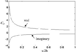
Previously, we have given the surface pressure coefficient variation for a vertically oscillating thin airfoil with Eq. 6.25 and the amplitude variation along the chord with Fig. 6.2. Now, the real and the imaginary parts of the surface pressure along the chord will be given by Fig. 6.6. Although, Eq. 6.25 which is based on the local linearization does not indicate the presence of the shocks at the leading and trailing edges, it gives agreeable results with experimental pressure measurements.
 |
 |
In order to describe the behavior of the surface pressure distribution of a thin airfoil in unsteady transonic flow, the effect of the increase in free stream Mach number must be considered.
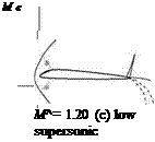
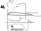
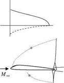
In this respect, it is possible to summarize and classify transonic flow conditions for a thin airfoil pitching in oscillatory motion with illustrations similar to that given in Fig. 6.7a-c, based on the experimental and the computational results, obtained for the surface pressure (adapted from McCroskey 1982). The low transonic flow conditions as shown in Fig. 6.7a indicate the presence of a shock on the instantaneous surface pressure distribution C0, and in a periodic motion the real and imaginary parts of the surface pressure Cp depicts a slightly moving shock which is called ‘shock doublet’ in literature. In addition, the appearance of a strong shock on the upper surface of the airfoil causes boundary layer separation. In Fig. 6.7b shown are the high transonic flow conditions where the free stream Mach number is very close to 1 and the real and imaginary parts are quite similar to that of Fig. 6.6 for which the local linearization technique is implemented. In the flow field for this case, we see the presence of k shocks around the trailing edges of the upper and lower surfaces. According to Fig. 6.7c in low supersonic flow regime, the instantaneous surface pressure distribution remains almost constant except around the leading edge which is the same for the unsteady surface pressure distribution. In the flow field of a low supersonic flow, a separated bow shock at the leading edge, and around the trailing edge a fork shaped shock at the upper surface and an expansion fan at the lower surface are present.
In unsteady flows when the viscous effects are negligible i. e. when there is not any shock separated boundary layer flow, the movement of the shock wave is observed for the low and moderate reduced frequencies. In these cases because of shock movement the linearized approach is not suitable. In high reduced frequencies, since the shock movement is not that high, it is possible to use linearized approach (McCroskey 1982). When the linear theory is not applicable either the local linearization or the full non linear potential equation is to be solved. For the cases of strong shocks the presence of vortices forces us to resort to the solution of Euler equations.
 |
|
 |
 |
M^ = 0.80 MM= 0.98
(a) low transonic (b) high transonic
Fig. 6.7 The surface pressure distribution and the flow fields for different transonic Mach numbers (* indicates sonic conditions)
In cases of strong viscous effects the presence of flow separation in transonic flows causes some unsteady phenomena such as ‘flutter’, ‘buffeting’ and ‘aileron buzz’ to happen. The flutter phenomenon as a shock induced separation occurring with the shock movement was first observed experimentally with the forced pitching oscillation of profiles. The self induced periodic shock movement on a thick biconvex airfoil in a transonic flow at zero angle of attack was first observed with numerical solutions, and then it was also observed experimentally for certain free stream Mach numbers and frequencies (McCroskey 1982). These observations were useful mostly for the assessment of transonic buzz which indicates the regular response of the structure to the aerodynamic effects. In 1970s, it was possible to predict experimentally the onset of buffeting for a profile with respect to the Mach number and sectional lift coefficient (Kuche – mann 1978). Shown in Fig. 6.8 is the enveloping curve b for the onset of buffeting depending on the free stream Mach number and the sectional lift coefficient of a profile. The conditions for the onset of buffet depending on frequency spectrum of the surface pressure oscillations, induced frequency and the size of the separation were experimentally determined starting from 1980s. On the other hand, starting from 1990s it has been possible to establish these conditions with numerical solution of Navier-Stokes equations using proper turbulence models. This requires very fine resolution for the computational grids so that the first point away from the surface lies in the viscous sublayer (Isogai
Fig. 6.8 Effect of freestream Mach number and the sectional lift coefficient on a flow separation, b buffeting, c drag divergence and d critical Mach number variation
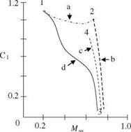 1992). In 2000s the numerical solution obtained with different turbulence models enabled researchers to predict the onset of buffet for NACA0012 at various angles of attack and free stream Mach numbers (Barakos and Drikakis 2000). According to Barakos and Drikakis for the Reynolds number range of 106-107 the 12% thick symmetric profile at zero angle of attack does not undergo any buffet up to the free stream Mach number of 0.8. On the other hand, at 1° angle of attack and at 0.8 Mach number, and at angle of attack range 2-4° for lower Mach numbers like 0.775 and 0.725 the buffeting starts. Most recent numerical studies on a supercritical airfoil, NLR7301, indicate buffeting at 0.5° angle of attack and in the free stream Mach number range of 0.82-0.83 and Reynolds number range of 1.943 x 10⁶-1.954 x 10⁶! This range is called ‘transonic dip’ and outside of this range no buffet is encountered (Geissler 2003).
Another unsteady transonic phenomenon is the ‘aileron buzz’ and it is due to a shock doublet created by the shock movement which causes hinge moments with dissipation at the hinges of aileron. The onset of buzz can happen with weak viscous effects but its maintenance requires strong viscous effects (McCrosky 1982). Both numerical and experimental results enable us to predict the boundaries of buzz with angle of attack and free stream Mach number. Accordingly, the buzz is encountered at lower transonic Mach numbers with increasing angle of attack. In recent years, numerical solution of Navier-Stokes equations performed for designing a ‘Supersonic Commercial Plane’ by the Japanese National Aerospace Laboratories gives a detailed study of aileron buzz (Yang et al. 2003). In the work of Yang et al., oscillation of an aileron of a wing at a zero angle of attack attached to a fuselage is studied numerically as fluid-structure interaction problem based on an aeroelastic-aerodynamic solution. In their study, a moving deforming grid is employed together with structural damping of the elastic wing. The elastic wing at free stream Mach number of 0.98 indicated undamped aileron buzz to increase the amplitude of oscillations in such a way that eventually the numerical solution diverged. During the diverging of the numerical solution, the amplitude of the oscillation of the angle rises from, 1 ° to 2° in one cycle. For the case of the rigid wing, however, the same flow conditions caused damping for the aileron
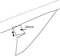 |
oscillations. For the free stream Mach number ranging from 0.95 to 1.02, the aileron oscillations showed damping behavior even for the elastic wing! (Fig. 6.9)


