Wake convection
 |
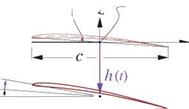
A major complication in calculation of unsteady flows is the evolution of the wake, both its doublet strength as well as its geometry. The physically correct wake shape is the streakline (in 2D) or streaksurface (in 3D) attached to the trailing edge. An example is shown in Figure 7.6 for a heaving airfoil. In the most physically accurate free wake case the wake shape’s evolution in time depends on the history of the velocity field of the airfoil+wake combination, and hence depends on the flow solution itself. This renders the problem nonlinear, since the kernel functions for the wake doublet sheet, in particular the r’ values in the pM integral (7.10), will now depend on the solution.
![]()
![]() Prescribed Wake, along TE path (linear flow problem)
Prescribed Wake, along TE path (linear flow problem)
Prescribed Wake, straight (linear flow problem)
Figure 7.6: Three different wake geometry models. In free wake model, spanwise wake roll-up typically occurs at locations of strong shed vorticity.
A further complication is that a free vortex sheet will in general undergo roll-up wherever the vorticity is concentrated. Steady flow problems which only have trailing vorticity typically have wake roll-up at the wake sheet’s wingtip edges, as sketched in Figure 5.4. Unsteady flow problems in addition also have roll-up caused by shed vorticity. The extreme deformation of the wake shape undergoing roll-up makes accurate tracking of this shape difficult and computationally expensive.
These complications associated with a free wake can be mostly eliminated by using the prescribed-wake assumption. Here the convection of the wake by the velocity field is ignored, and instead the wake geometry is prescribed explicitly. Two possible choices are shown in Figure 7.6. The simplest straight-wake assumption is quite adequate for modest airfoil motions, and is almost invariably used by Vortex-Lattice methods. The great advantage of a prescribed wake is that it renders the potential flow problem linear, since the kernel functions then become independent of the flow solution. Unless the rolled-up wake closely interacts with a downstream surface, the neglect of roll-up generally results in very minor errors in a potential flow solution.
3.1.4 Panel method formulation
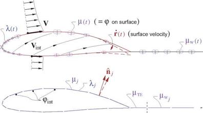
Figure 7.7 shows the velocity field relative to the body, both on the exterior and the interior. These are defined as
V(r, t) = —U — О x r — Г + Vgust + Vp (physical exterior velocity) (7.28)
Vint(r, t) = —U — ° x r — Г + Vgust (nonphysical interior velocity) (7.29)
where only Vp is unknown a priori. The physical flow-tangency requirement on the exterior is
V ■ A = 0 (7.30)
so that the source sheet strength is
which is known and thus can be explicitly specified for each point on the body surface.
If we now specify a zero interior potential, pint = 0, the doublet sheet strength then becomes the physical external perturbation potential p, while on the wake it represents the physical jump др.
F = P – Pint = P (7.32)
Fw = Др (7.33)
|
Figure 7.7: Body-relative exterior and interior velocities represented by body motion, gust field, and surface source and doublet sheets, shown in top figure. Panel discretization of the sheet strengths is shown in the bottom figure. |
The zero interior potential is imposed via Green’s identity
v™ = d5 + + i/AfwVG)’n d5w = 0 (734)
which after evaluation on the paneled geometry becomes the following matrix equation for the unknown surface-panel doublet strengths Fj.
Aij Fj = – Awj Fwj – Bij Aj (7.35)
The trailing edge wake panel strength at each spanwise location is an unknown, but is related to the two top and bottom surface strengths at the trailing edge at that same location.
FwTE (FJTE )u + (FjTE )l (7.36)
This is equivalent to a Kutta condition.
The unsteady solution proceeds in a sequence of time steps, with the following operations performed at each time step:
1. Set the source panel strengths A j from the known Vint (r, t).
2. Set all the wake-panel doublet strengths FWj- from the previous time step, by convecting Fw without change along Va, according to the zero wake-load condition.
DPw _ „
Df
A common approximation made here is to assume
V ^ -(U + Oxr)
which is computationally simpler and much less expensive to evaluate.
3.  Evaluate the righthand side in (7.35) using the known Aj and pw.
4. Solve linear system (7.35) for pj, using the same LU-factored A. matrix for all time steps.
5. Using pj, pWj, A j, evaluate ф, Vp, V on surface, compute pressure and airloads.
For a much more detailed description of the necessary calculations see Katz and Plotkin [4].
The 3D unsteady panel method described above is quite general, but provides little insight into unsteady flow behavior except via numerical experimentation. Hence we will next consider simplified models of several specific unsteady flows of interest. Suitable approximations will be used as needed to obtain more concise semi-analytical results for unsteady aerodynamic forces and moments.


