The Vortex Lift (Polhamus Theory)
Classical two dimensional aerodynamics based on the potential theory states that the leading edge suction cancels the streamwise component of the normal force so that there is no drag force acting on the airfoil. In other words, the leading edge suction obtained by the potential theory can overcome any form of drag except the
![]()
viscous drag. This makes us wonder if we can make use of the leading edge suction for creating useful aerodynamic forces under special conditions.
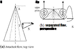
It has been observed that the wings with high leading edge sweeps at high angles of attack generate such a high lift that can not be predicted with potential theory. The reason for that is at high angles of attack the vortex generated at the leading edge due to separation merges with the tip vortex to create a strong extra suction force at the upper surface of the wing. This additional lift is called ‘vortex lift’ and it is predicted with the ‘leading edge suction analogy’ by Polhamus by early 1970s (Polhamus 1971). This theory is very much in agreement with the experiments, and it is also called Polhamus theory after its validity was proven on delta wings having low aspect ratio. Now, we are ready to study the vortex lift generation with the aid of Fig. 8.9. According to the potential theory the sectional lift coefficient of a thin airfoil in terms of density, freestream speed and the circulation was given by Eq. 1.1 as I = pUC. We can resolve the lifting force I into its components in the direction of the chord and direction normal to the chord. The normal force is denoted by N, and the force in the direction of chord is called the suction force S. The suction force S, here, is the result of the low pressure zone on the upper surface of the airfoil caused by the fast moving flow. Accordingly, if the angle of attack of the airfoil is a, then the suction force will reads as S = pUTsin a. For a profile with a sharp leading edge even a small angle of attack will cause the flow to separate from the leading edge (Fig. 8.9d). The vortex generated by this separation will create a leading edge suction force S which will now be normal to the surface as opposed to the leading edge suction force of the attached flow.
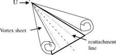
This leading edge suction force creates the extra lift for the wing. For suction force S to be sustainable, the leading edge vortex must merge with wing tip vortex in a stable and steady fashion. The leading edge vortex shown in Fig. 8.10 merges with the tip vortex to form a reattachment line on the upper surface of the wing which has a stable circulation providing continuous extra lifting force.
 |
 |
||
Let us use the effective circulation Г and the effective span h of the wing given by Fig. 8.11. If we consider the thrust force T generated by the leading edge vortex, and the adverse effect of the induced downwash wj we get T = pTh(U sin a — wi). Now let us define a non dimensional coefficient Kp related to the potential flow for a wing whose surface area is A as follows
Fig. 8.10 Leading edge vortex sheet and the reattachment line on the upper surface of a delta wing
 Kp — 2Ch/(AU sina).
As the non dimensional thrust force CT of the thrust force T we have
![]()
![]() Kpsin2a.
Kpsin2a.
![]()
![]()
Using the potential lift coefficient Kp we can write non dimensional lift coefficient as CL, p = CN, p cos a = Kp sin a cos2 a. Figure 8.11 gives us the relation between the suction force S in terms of thrust force T as S = T/cos Л, where Л is the sweep angle of the leading edge. The vortex lift coefficient CL, v after the leading edge separation reads as
The addition of potential and vortex lift gives the total lift coefficient CL as
CL — Kpsinacos2a + Kysin2acosa. (8.10)
Here: Ky = (1 – ui^)Kp/cosK.
 |
||
According to Eq. 8.10, at low angles of attack the potential term, the first term of the right hand side, and at high angles of attack the vortex term which is the second term plays a dominant role in the lift. For the low aspect ratio wings at angles of attack lower than 10° Eq. 1.11 gives a lift proportional with a. Similarly, with assumption of small angle of attack we predict the lift proportional with the angle of attack using Eq. 8.10.
In Fig. 8.11b, shown is the spanwise variation of the upper surface pressure coefficient created by suction force S by the separated flow on the upper surface.
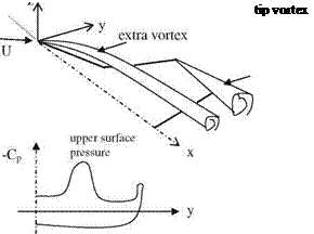
In practice, in order to increase the manipulability at high angles of attack using leading edge extension at the root of a wing with moderate sweep creates a new vortex lift (Polhamus 1984; Hoeijmakers 1996). The extra vortex generated by the leading edge extension is shown in Fig. 8.12 with the associated surface pressure coefficient on the upper surface of the wing. Even at moderate angles of attack, the presence of the extra lift contributing to the total is seen in the pressure spanwise distribution. In addition, we observe from the surface pressure curve that the extra vortex creates a strong suction on the upper surface of the wing.
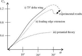
With the aid of Figs. 8.11 and 8.12, we have studied the effects of vortex formation at high leading edge sweep and the leading edge extension of the wings on the spanwise distribution of surface pressure coefficients. Now, we can see the formation of a strong vortex on the total lift coefficient of the wing. Shown in Fig. 8.13 is the total lift coefficient change of a wing with the angle of attack.
The curve in Fig. 8.13 indicated as the potential theory lift curve is obtained by using the first term of Eq. 8.10. In delta wing, on the other hand, both terms of Eq. 8.10 is used in obtaining the lift coefficient curve, where as the leading edge extension lift curve is adopted from Polhamous and Hoeijmaker. In addition, deviation from the Polhamus theory and the experimentally obtained lift loss is shown in Wentz and Kohlman (1971) and Polhamus (1984). Three dimensional wing theory predicts that the induced drag force is proportional with lifting force. The leading edge vortex increases the lifting force, and induces a drag force proportional with the tangent of the angle of attack (Wentz and Kohlman 1971). Accordingly, the total drag coefficient reads as
Cd = cd0 + Cxtana (8-ll)
 |
 |
where CD0 is the drag at zero angle of attack.
In the Chap. 4, the Jones theory provided the lift generated by the cross flow over thin delta wings in incompressible flow. Now, we are going to study the effect of compressibility both in small and large angles of attack. In subsonic flow, depending on Mach number the Prandtl-Glauert formula provides the aerodynamic coefficients (Eq. 1.15a).
In supersonic flows, however, the leading edge sweep angle determines the formula to be used. If the leading edge of the outside of the Mach cone, i. e. supersonic leading edge, the Ackeret formula is sufficient (Eq. 1.20). If it is in the Mach cone, subsonic leading edge, the interaction between the upper and lower surfaces has to be taken into account (Puckett and Stewart 1947). In their study, the leading edge sweep angle Л and the Mach number M are used defining the parameter m as follows:
![]() (Vm2 — 1^ cotK
(Vm2 — 1^ cotK
and for m < 1
![]() – = 2pcot K/E(m’). da
– = 2pcot K/E(m’). da
Here, m’ = V1 — m2 and E(m’) is the elliptic integral of second kind (Korn and Korn 1968). If we write Eq. 8.12 suitable for the supersonic flows using Polhamus theory then the potential lift line slope reads as
![]()
 |
 |
Kp = nAR/[2E(m’)].
The vortex lift line slope Kv in terms of potential lift line Kp with the aid of Fig. 8.11 becomes
![]()
|
|
|
|
then for the supersonic
Kv = p[(16 — (AR * b)2)(AR)2 + 16)]1/2/[16 *(E(m’))2}. (8.15)
Here, b = PM2 — 1.
Since the supersonic flow is three dimensional, the induced drag force coefficient for m < 1 and small angles of attack becomes (Puckett and Stewart 1947)
Cdi = aCl[1 – m’/2E(m’)] (8.16)
Example 1 Euler Equation numerical solver for a delta wing with 75° sweep at M = 1.95 and 10° angle of attack gives the normal force coefficient as CN = 0.295 (Murman and Rizzi 1986). Find the normal force coefficient with:
1. incompressible potential flow
2. supersonic potential flow,
3. Polhamus theory.
Solution:
1. For M = 0: we find CN = p/2ARa cos a = 0.289.
2. For M = 1.95: Kp = 2p cot A/E(m’), m = pM2 — 1 cot A = 0.4485, and sin – (1 – 0.4485 / = 63.35, E(63.35) = 1.18 (CRC 1974) Kp = 1.446. This gives CNp = 0.235.
3. According to the Polhamus theory the extra lift created by the leading edge vortex reads as Kv = p [(16 – 1.1487 x 2.8025) (1.1487 + 16)]^/(16 x 1.182) = 2.087, and CN, p = CL, vcos 10 = 0.061. Total normal force coefficient: CN = CN, p + CN, v = 0.235 + 0.061 = 0.296.
Accordingly, the closest solution to Euler’s result is obtained with the Polhamus theory.
Example 2 Find the induced drag coefficient of the wing given in Example 1. at 10° angle of attack.
Solution: CDi = 0.033 from Eq. 8.16.
The viscous and total drag forces acting on the swept wings are given in much detail in Kuchemann (1978).
The extra lift created by the leading edge vortex of a delta wing with small aspect ratio is not sustainable, as shown in Fig. 8.11, when the angle of attack increases beyond a critical value because of the spoiling of the symmetry of the vortex pair. Once the symmetry of the vortex pair is broken, the amount of suction on the left and the right side of the wing are no longer equal, therefore, there emerges a non zero moment with respect to the axis of the wing. This moment causes wing to start a rolling motion which is referred to as wing rock.


