Vortex Wake Considerations
Despite the various assumptions and approximations used with the BEMT, validation studies have shown it can give good preliminary predictions of turbine loads and performance [see Hansen (1993)]. It also offers considerable insight into basic design parameters affecting the turbine performance, including blade geometric parameters such as planform and twist. Under yawed conditions, however, the BEMT is less able to model the physics of the turbine aerodynamics because of the strongly nonaxisymmetric flow and the 3-D nature of the airloads produced over the turbine disk; see Schreck et al. (2000) for a comprehensive discussion. A major source of this three-dimensionality is the vortical wake system produced behind the turbine, a visualization of which is shown in Fig. 13.20. Like a helicopter, the turbine wake is comprised of strong vortices that trail from each of the blade tips and these are rendered visible in this photograph by the use of smoke generators. Because a wind turbine extracts energy from the wind, the wake expands downstream of the turbine. It may also distort as a result of the wind gradient and turbine yaw angle. While flow visualization of the wake downstream of a wind turbine is relatively rare, a good review
|
Figure 13.20 Photograph of the vortical wake behind a horizontal axis wind turbine rendered visible using smoke injection. Notice the skewed wake resulting from the wind gradient and the effects of the tower shadow. Source: Photo courtesy of NREL. |
of the field and survey of existing results is given by Vermeer et al. (2003). See also Grant et al. (2000) and Vermeer (2001) for a discussion of the general characteristics of wind turbine wakes.
Various modifications to the blade element approaches have been used to represent these 3-D wake effects, for instance, by using inflow models, some of which have been derived from helicopter applications (see previously in Section 3.5.2). While improvements in predictions of net power are usually obtained using these methods, their ability to predict blade loads over an acceptably wide range of operating conditions or for new wind turbine designs is not very satisfactory; see Fingersh et al. (2001). A more rigorous treatment of the turbine wake requires a method that can represent the strengths (circulation) and spatial locations of the vortical elements that are trailed by each blade and convected into the downstream wake. This can be done using vortex methods, which have become very popular tools for the analysis helicopter wake problems. (See Section 10.7 for the fundamental theory of vortex wake methods.) The development of a vortex wake model is usually based on the assumption of an incompressible potential flow, with all vorticity assumed to be concentrated within vortex filaments. From the strengths of the vortex filaments (determination of which requires proper coupling to the blade lift distribution), the induced velocity field can be obtained through the application of the Biot-Savart law (Section 10.7.1).
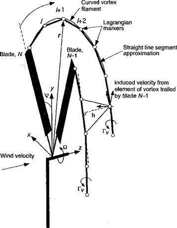
The idea of a vortex model applied to the wake of a wind turbine is shown schematically in Fig. 13.21. Vortex methods applied to turbine wake problems can be categorized into “prescribed” or “free” vortex techniques, just as they are for helicopters (see Section 10.7). A prescribed vortex technique is v/here a discrete representation is made of the vorticity field, but the positions of the vortical elements are specified a priori based on semi-empirical rules – see Robison et al. (1995). Prescribed vortex methods can be viewed more as postdic – tive rather than predictive methods because they use experimental results for formulation purposes and so are strictly limited in scope to the conditions that encompass the range of measured operating conditions for which they were originally formulated. The free-vortex method (FVM) is a predictive method because the elements are allowed to convect and deform freely under the action of the local velocity field. While a disadvantage of all types of vortex methods for modeling the wake is their relatively higher computational overhead (mainly because of the need to evaluate the Biot-Savart law a very large number of times), they are an inherently more appealing physical approach for modeling the wake than the use of inflow models.
Prescribed vortex wake models have seen some use for wind turbines, e. g., Kocurek (1987), Robison et al. (1995), and Coton & Wang (1999). The development of more generalized prescribed wake models for wind turbine applications is a significant undertaking because not only do the positions of the wake vortices need to be documented, but the experimental conditions must encompass a wide range of turbine geometric (e. g., blade shape and twist) and operating states (wind speed, yaw angle, etc.). Therefore, a trade-off must be drawn between the costs of doing more experiments and collecting more data to build the model, and the costs of developing a better and more flexible model that can be validated against existing data. Prescribed wake models are also only strictly applicable when the operating conditions are nominally steady-state, that is, in a steady wind (which never exists in practice). Free-vortex methods have fewer potential limitations when applied to new turbine designs and/or more general operating states. Such methods are yet to see significant use for wind turbine applications, but offer much more rigor than the ad hoc application of “inflow” models derived from helicopter rotor models, especially because these have not yet been validated for all of the flow operating states of a wind turbine.
|
Figure 13.21 Modeling the downstream wake of a wind turbine using a free-vortex filament method, with vortices shown trailing from the tips of each blade. |
Free-vortex methods are based on a discretized, finite-difference representation of the governing equations for the wake and, when solved, track the evolution of discrete vortex elements through the flow. The number of discrete elements can be in the thousands, making the tracking process memory intensive and computationally demanding, although still considerably less demanding than when using the various types of CFD methods solved on Eulerian grids (described in Chapter 14). The vortex wake method must be supplied with boundary conditions that relate the lift (bound circulation) on the blades to the strengths of the trailed vortex filaments. This is usually done by using a lifting line or lifting surface model, such as discussed in Section 14.9. Experience suggests that the FVM generally gives better predictions of blade loads than is possible with prescribed or rigid wake models. It can also, in principle, deal with transient problems such as when the turbine yaws into and out of the wind – all the wake dynamics can be accounted for in a time-accurate manner without having to make assumptions about the effects on the wake geometry or the time constants of the flow. Under transient conditions, the plane of the turbine may yaw momentarily into its own wake, raising the complexity of the problem of defining the induced velocity field even further.
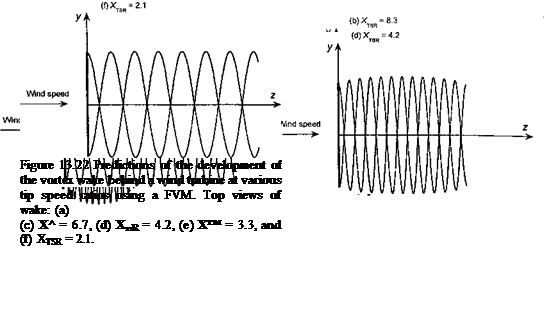 |
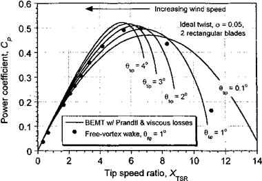
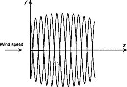
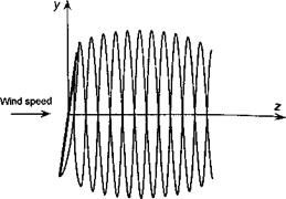
Representative examples of time-accurate FVM wake calculations for a HAWT are shown in Fig. 13.22. In both cases, the wake geometry is shown for a two-bladed HAWT operating in a steady wind speed at different tip speed ratios. Figure 13.22 shows top views of the wake geometry for zero yaw angle, with predictions of the corresponding power output in Fig. 13.23. At high tip speed ratios (low wind speeds) the induced velocity at the turbine is a large fraction of the wind speed and so the turbine operates in the vortex ring state. This can be seen in Fig. 13.22(a) by the accumulation of wake vorticity near the turbine disk. Increasing the wind speed causes the wake to develop into the turbulent wake state [see Fig. 13.22(b)], which is characterized by a wake instability and turbulence downstream
|
Figure 13.23 Power coefficient as a function of tip speed ratio using vortex wake and BEMT theories. |
of the disk. As the turbine approaches the point of maximum efficiency for XTSR « 6 notice that the wake expands downstream of the disk because at this condition the turbine is now extracting maximum energy from the wind and slowing (braking) the flow. As the vortices age, they diffuse under the action of viscosity and turbulence (see Section 10.6.2) and the wake slowly begins to contract again. Further decreases in XTSR cause the wake to convect more quickly downstream, and then the wake expansion decreases as the power output drops.
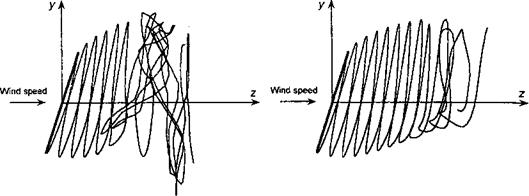
Figure 13.24 shows time-dependent FVM calculations where the turbine quickly yaws 30° out of wind from an initial operating condition near to its peak efficiency. Such a situation can also be produced when the wind direction changes. This serves to illustrate several points about wind turbine performance, in particular the nonuniformity of the inflow and the unsteady aerodynamic effects produced in the wake when the turbine continuously yaws into and out of the wind. Initially, just after the yaw starts, the turbine blades move into their own wake. This is a situation where there can be relatively powerful interactions between the blades and discrete vorticity in the wake, leading to highly unsteady local blade loads. However, these blade-wake interactions are not as severe as those found on helicopters. Notice that the adjustments to the developing wake take place relatively slowly, with the older part of the wake disintegrating and the new part near the rotor continuously evolving. Only after about ten turbine revolutions does the solution become essentially quasi-steady and periodic once more. In this condition, the component of wind velocity parallel to the plane of the disk begins to skew the wake, which induces a velocity field that causes the wake to roll up along its top and bottom edges. This is another source of the gradient in the induced velocity across the plane of the disk that inflow models (such as Eq. 13.63) attempt to mimic.
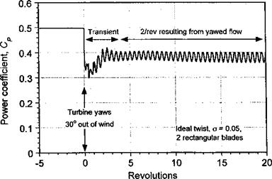
The corresponding time-history of the power output from the turbine under these conditions is shown in Fig. 13.25. Notice that the power output drops rapidly by an amount that is proportional to the cube of the change in yaw angle, as would be suggested by Eq. 13.2. In this case, an initial 35% reduction in power output is caused by the 30° yaw misalignment to the wind. Thereafter there is some recovery in average power output as the wake structure
![]()
|
|
|
|
|
|
|
|
|
reorganizes and the inflow velocities over the turbine disk reach an equilibrium. These nonsteady inflow effects are often modeled in wind turbine analyses using variations of dynamic inflow theory, an approach discussed previously in Section 10.9. The idea is to consider the unsteady aerodynamic lag of the inflow development over the turbine disk in response to changes in blade pitch inputs or changes in turbine thrust. The equations describing the distribution of inflow are written in the form of a set of ordinary differential equations, with a time constant (or constants) representing the dynamic lag in the buildup of the inflow. Dynamic inflow models mathematical form and relative numerical efficiency, and their predictive success for various applications in the helicopter field are attractive because of their simplicity (see Section 10.9). However, the models have not been rigorously validated for rotors operating in the windmill state, although see Houston & Brown (2003) for some further insight into this issue. The main advantage of representing the aerodynamic model as sets of ordinary differential equations is that this form is appealing for many structural dynamic and aeroelastic analyses of the wind turbine, and this formulation of the inflow model allows the entire coupled problem to be solved simultaneously using the same numerical methods. For a discussion and background of dynamic inflow models applied to wind turbine problems see Bierbooms (1991), Snel & Schepers (1991), Hansen & Butterfield (1993), and Snel (2001). Bierbooms (1991) and Snel & Schepers (1991) suggest specific values of the wake time constants for wind turbine work, based on empirical evidence of the “induction lag.” Based on the results from the FVM the complexity of the physics of the unsteady wake problem cannot be underestimated. Yet, if the time constant(s) of a dynamic inflow model can be obtained, say using time-accurate vortex-wake calculations suitably validated with controlled experiments, then this approach provides a particularly useful form of parsimonious model that can relate changes in turbine loads to the lag in the inflow development.


