Propulsive lifting bodies
It is fairly clear by now what the properties should be of the combined flowfield generated by volume, lift, and propulsion: the compressions caused by volume and lift should be used in the first stage of the flow cycle with heat addition; the expansion stage of the flow cycle should be accomplished without introducing further shockwaves which cannot be utilised also for the provision of volume and lift; and all this should be achieved within a large number of constraints and extra conditions, such as heating, which include not only requirements for overall values for volume, lift, and thrust minus drag, but also details concerning their distribution over the body. However useful such a fully-integrated propulsive lifting body may be, the close integration of so many design parameters makes it difficult to establish a general and comprehensive design theory; an ‘aerofoil theory’ as for the other types of aircraft does not yet exist for wave – rider aircraft. All we can do here is to demonstrate some general design principles by means of specific examples.
At first sight, there seems to be a fundamental contradiction in this integration: we have seen that aerodynamically efficient lifting bodies generate rather weak shockwaves, whereas flow cycles with heat addition are traditionally considered to need strong compressions, which can readily be generated in high-speed flight and are one of its attractions. We shall see later that this apparent contradiction can, in fact, be resolved.
With propulsion in mind, we may want to give the body a blunt nose with a strong shock and add heat there. H F Lehr (1972) has demonstrated that such a flow is physically possible and that steady Chapman-Jouguet detonations can be generated in a hydrogen-air mixture at Mach numbers around 5, as long as the velocity of the body is not below detonation velocity, when pulsating detonations occur. (He also demonstrated the existence of steady deflagration fronts attached to the nose of a conical body.) However no thrust force was produced; instead, the drag was increased by heat addition at the nose of a blunt body. This result is only to be expected. It has been confirmed by a calculation of the simple flow of a combustible fuel-air mixture past a twodimensional double-wedge section at a Mach number of 5. A detonation wave, operating at the Chapman-Jouguet point, is assumed to be attached to the leading edge. The thermal efficiency of the flow cycle is quite good, at nth ~ 0.29 . But the drag is doubled, from Cq « 0.05 to 0.10, because of the large increase in pressure over the forward-facing surfaces due to heat addition. Thus nose burning does not appear to be suitable for practical purposes, although there may be exceptions: if the body is very blunt and has a very high drag, then this drag may be reduced by nose burning, just as nose blowing may do (see P J Finley (1966)). This has been shown theoretically by W Schneider (1968) and experimentally by F Maurer & W Brunge (1968). Here, we look for other ways of adding heat to the flow past a body which itself has a low drag.
A profitable line to follow is the addition of heat in a region of the flow – field where the body alone has an expansion, with the aim of eliminating it.
If we think of a lifting body like a caret wing but with the afterbody modified to sweep upwards to a sharp trailing edge, then a good place for burning is on the lower surface of the afterbody, where some compression has already taken place upstream of it. The heat addition itself may again be thought of as either a detonation wave, assuming premixing of fuel and air is feasible, or as a diffusion flame. The suitability of afterbody burning was first recognised by К Oswatitsch (1959) and its physical existence has been demonstrated by experimental results such as those reported by G L Dugger (1959). Base burning, which has already been discussed, may be regarded as a special extreme case of afterbody burning.
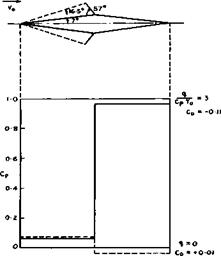
We may again consider a simple flow of this kind, that of a combustible fuel – air mixture past a twodimensional double-wedge section, but now with a detonation wave, operating at the Chapman-Jouguet point, assumed to be fixed at the ridge line, with a strength and inclination which turns the flow behind the bow shock back along the afterbody, as sketched in Fig. 8.33. We take the
|
Fig. 8.33 Wedge flows at Mg = 5 without and with afterbody burning assuming onedimensional detonation characteristics |
values behind the detonation wave as for a onedimensional flow, although we know that the characteristic direction in the flow immediately behind the wave lies along the wave so that the unknown, and neglected, wave beyond the intersection between bow shock and detonation wave will influence the flow over the whole afterbody. The results in Fig. 8.33 show that the initial expansion would be completely eliminated and the pressure enormously increased over the afterbody, in this simple approximation. The body would experience a large negative drag and the thermal efficiency would be nth “ 0.40 and the propulsive efficiency Лр =0.38 .
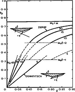
Other instructive examples of flows with external heat addition, which demonstrate effects of the mainstream Mach number, have been given by К Oswatitsch (1959) and J Zierep (1966). Both consider wedge-type twodimensional bodies with a flat top along the mainstream, with heat addition in some form over the lower surface of the afterbody, as sketched in Fig. 8.34. Oswatitsch
 LIVE GRAPH
Click here to view
![]() Approximate propulsive efficiencies for afterbody burning
Approximate propulsive efficiencies for afterbody burning
considers the case where heat, q, is added over an area adjacent to the rear of the body and assumes that both the wedge angle 6 and q are small and that the equations of motion may be linearised. The change in pressure caused by the heat input can then be determined and from it the propulsive efficiency. A simple analytic expression is obtained:
Zierep considers the case where heat is added along the first right-hand characteristic line, which passes through the shoulder of the body, up to a point from where the left-hand characteristic line just passes through the trailing edge (a further extension would not affect the pressure over the body and heat would be wasted). Zierep considers a non-linear hypersonic approximation and assumes that 6 <( 1 and (Mq6 )2 > 1 . Again, an analytic expression for the propulsive efficiency can be derived
ГИи
b +
The results in Fig. 8.34 show that the propulsive efficiency increases considerably with increasing Mach number (the same trend as in Fig. 3.16) and with increasing wedge angle (i. e. with increasing pressure at combustion).
 |
|||
The latter implies, of course, that the drag over the forebody also increases. Thus a complete answer indicating the overall aerodynamic efficiency can only be obtained from a consideration of the whole flowfield or from the pressure distribution over the whole surface, not from the propulsive efficiency alone. We also see from Fig. 8.34 and equation (8.30) that the propulsive efficiency is bounded and cannot exceed the value
in this particular flow. This reminds us of the fact that the overall heat input in onedimensional flows is also bounded, equation (8.26). The full implications of this fundamental physical limitation in practical designs is not yet clear.
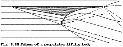 |
We can now establish some of the general features which a propulsive lifting body with external heat addition will have. A possible simplified scheme is shown in Fig. 8.35. This may be thought of as a section of a twodimensional body or, alternatively, as the centre section of a caret-like threedimensional body derived from it, because the design principles discussed in section 8.2 still apply. It is assumed that it is not worthwhile to generate lift on the upper surface, and so all the important events are confined to the lower surface. One shockwave over the forebody provides lift, as on a caret wing, and also the pressure rise needed for adding heat, assumed to take place in a
suitably inclined plane. Downstream of that, the flow expands in a fhalf – openr nozzle and the shape of the lower surface of the afterbody will, in general, be curved. If freestream pressure is not yet reached at the trailing edge, which is assumed to be sharp, then at least one upper shockwave and a lower expansion fan will emerge from there. Another expansion fan will start at the lower end of the heating zone to adjust the pressure and flow direction to that behind the oblique shockwave which also starts at that point, as does a shear layer which divides the heated stream from the mainstream air. It is not likely that effects of viscosity will change this flow pattern in its essentials, although there may be a significant upstream influence of the trailing-edge shock. It is clear that a body as in Fig. 8.35 will provide volume and generate lift and that the pressure drag may have a sufficiently high negative value to overcome the viscous drag. We can also readily think of variants of this general scheme, which may be more practical or more efficient. For example, it may be more efficient to achieve a required compression through several shocks rather than a single shockwave.
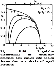
To get some idea of how much difference the shock system makes, we follow L H Townend (1966) and assume the inflow compression to be caused by a number, n, of oblique shocks. These are chosen to be of equal strength because equal-strength shocks give maximum pressure recovery for given n ; n ■ « then describes the isentropic compression. We assume that heat is added at constant pressure. All the properties of the flow cycle can then be determined in closed form, as for the constant-pressure cycle in section 3.6, but now as they depend on the parameter n (for details see the original paper or section 6 of D KUchemann & J Weber (1968)). We reproduce in Fig. 8.36 some results for the propulsive efficiencies for fixed values of the mainstream Mach number and of the temperature ratio, T2/TQ, at the end of combustion. This temperature ratio has been limited to indicate that real-gas effects are meant to be avoided. Пр is seen to have a maximum value which depends on the value of n. This decreases considerably as the number of shocks is reduced. (The values for n = « in Fig. 6.35 correspond to the curves in Fig. 3.16). That there is such a maximum follows from the facts that a certain heat input is needed to overcome the inflow losses before a thrust is obtained, and that the heat input itself is limited. Thus inflow losses tend to bring us away from the extremely lean fuel-air-mixtures desirable in an ideal flow cycle.
 LIVE GRAPH
Click here to view
The shock losses in the inflow manifest themselves as both thrust losses and increases in specific fuel consumption. For a discussion of how these can be determined, we refer to section 9-3 of D KUchemann & J Weber (1953). Here, we illustrate this important fact by a numerical example by comparing values obtained for n = 3 with those for an isentropic inflow (suffix i), for Mq = 10 and a constant cross-sectional area at the beginning of combustion.
The local Mach number there is then Mj = 4 and q/CpTg = 5 . The propulsive efficiency has fallen to Пр/Лрі = 0.84 . The pressure at the beginning
of combustion has fallen from рц/рд = 280 to P]/Pq = Ю0 . This is still
a very large value compared with those of turbo-jet engines operating at lower speeds; it shows the potential advantages of supersonic combustion.
The relative increase in specific fuel consumption due to inflow losses is 19% and the relative thrust loss is 71%. That the relative thrust loss is so much greater than the increase in specific fuel consumption is partly a consequence of the assumption that the front end of the combustion region has always the same size (i. e. Aj = A|. Inflow losses then reduce not only the pressure at which heat is added but also the mass flow through the combustion region. We conclude that we must not only aim at keeping the inflow losses small but also adjust the size of the ‘engine’ with a view to reducing the thrust losses, which in turn must be balanced against possible drag and weight increases and changes in lift and volume. This design process cannot be carried out without considering the propulsive lifting body as a whole.
Only a beginning has been made to clarify design aims and methods for complete propulsive lifting bodies, and we refer to the discussion of some simple cases in section 4.5 of D KUchemann (1965) and section 6.4 of D KUchemann &
J Weber (1968). An important aspect of the design of complete aircraft is the possibility of deflecting the thrust vector downwards. This has been investigated by J Pike (1971), who concluded that an efficient hypersonic cruising aircraft will have a significant fraction of its weight carried by the deflected jet generated by the heat addition. He derived a relation for the inclination of the propulsive jet, for certain optimum conditions. A considerable advance towards our aim was made in a series of papers by E G Broadbent (1969), (1971), and (1973). He developed an exact numerical method for calculating invisaid heated flows in twodimensions, which is practical and very fast on a computer. The method may be regarded as an essential first step which opens the way to various extensions: to the design of threedimensional propulsive lifting bodies; to make an allowance for the mass of the fuel, which may add significantly to the thrust; to include the effects of viscosity; and to take some account of the fuel-air mixing and of the chemistry of combustion. All this still remains to be done.
Broadbent uses an inverse method for solving the equations of motion. This approach is unfamiliar but has proved very successful. It is to prescribe the streamline pattern and then to calculate the distribution of heat sources needed to make the streamline pattern real. The resulting pair of equations in flow speed and pressure are linear hyperbolic equations with real characteristics along the streamlines and their orthogonal trajectories. The success of the method rests on this important property. It implies that numerical results can be obtained by marching along these characteristics from known conditions. This is done by putting a grid over the region of heating, with gridlines following streamlines and normals. Conditions are assumed known along the upstream normal and, in addition, one of the variables along one of the streamlines must be prescribed.. This, in fact, is just what we want to do in designing a body, because it enables us to choose the pressure distribution along part of the wall. The procedure is that the equations are first solved throughout the grid for pressure and flow speed and then the density distribution over the whole region is calculated from continuity. This, together with the pressure distribution, determines the state of the gas throughout the region, whence follows the enthalpy and hence the heat supply required. Most important, we obtain a complete flowfield and, by integration, the lift and thrust and drag forces as well as the volume capacity of the body. The procedure can readily be repeated and adaptations made, if the results do not seem to be satisfactory, for instance, if it turns out that negative heat sources are required or if the thrust is not large enough. The method is, therefore, especially suitable for the early project stage of an aircraft design and allows comparisons to be made between the performance characteristics of a wide range of these intricate and complex shapes.
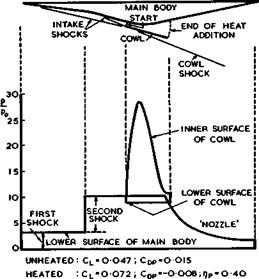
An example of Broadbent’s calculations is shown in Fig. 8.37. The main body
|
M0=7S
Fig. 8.37 Propulsive lifting body with heat addition within a duct. After Broadbent (1971) |
is again flat on top and along the mainstream at Mq ** 7.5 . It has a crosssection roughly like a double wedge. The forebody is shaped to produce two shockwaves which would be followed by an expansion over the afterbody in the absence of heat addition. The body would then experience a small lift and a large drag. In this example, a solid cowl is added to the bodies, which begins at the point where the two ‘intake shocks’ intersect, and heat is added inside the duct so formed between the cowl and the body. This cowl was introduced by Broadbent because he found that purely external heat addition generally had a poor propulsive efficiency. Also, the mean pressure over the forward-facing surfaces was usually greater than that over the rearward-facing surfaces, and the net pressure drag was found to be positive, even though the heat addition greatly reduced it. Now, the pressure distributions in Fig.
8.37 indicate how the expansion is completely eliminated by specifying the pressure over the lower surface of the main body to remain constant at the
value behind the second intake shock. The pressure falls in the half-open nozzle downstream of the duct, but it stays positive. A large force is seen to act on the cowl: this contributes to the thrust force, at the expense of
some negative lift. However, the overall lift is considerably increased by the heat addition and the coefficient of pressure drag, Сдо , is now negative at a value which should be ample to overcome friction forces in steady flight, and which might allow some acceleration of the vehicle. But since the development of the boundary layer has not yet been investigated, and since no experiments on this general scheme have been carried out, it is not clear whether the flow can be realised in practice. In particular, it should be checked whether the boundary layer on the main body and that on the inside of the cowl will stand the pressure rises through the second intake shock and that behind the cowl lip.
The propulsive efficiency rip = 0.41 is quite good; it is somewhat below but not far short of that of constant-pressure cycles with intake shock losses discussed in connection with Fig. 8.36. But then this particular example does not in any way present the best that can be achieved. Broadbent has calculated many more cases which give some clear indications of desirable aims and how these may be achieved. For instance, one way of improving the lift-to – drag ratio and the propulsive efficiency beyond those of the body with the straight cowl in Fig. 8.37. retaining the same two-shock intake, is to curve the cowl towards the body in such a way as to provide an expansion behind the cowl shook. One such section has given the following excellent set of values: – 0.084, Сцр “ -0.031, and rip = 0.66 at a maximum temperature of about 3000 K, at Mq – 7.5 . Another way of achieving improvements is to incorporate a third shockwave, attached to the lip of the cowl. Whereas the first two wedges deflect the flow downwards, the third cowl shock deflects the flow upwards. This leaves the cowl set at a relatively small angle to the mainstream, and the net thrust may be improved at the cost of some loss in lift, because of the heavy download on the cowl. The propulsive efficiency is then generally between 0.6 and 0.7. There is obviously no limit to the number of variations that could be made, and it would seem advisable to bring in some practical constraints in further steps to be taken.
Very little work has as yet been done on stability and control problems of hypersonic flight and on the flight dynamics of the integrated waverider aircraft we have in mind. Some problems arising when control surfaces are deflected have been mentioned in section 8.4. Some stability and control problems have been discussed by R Ceresuela (1971) (see also F L Roe et al.
(1971) ). It may also be possible to read across from the many results obtained for the present generation of space shuttle orbiters.
It seems also worthwhile to explore the possibilities of using the propulsion system for control purposes. Thrust deflection, which has already been mentioned, is one of these. But we have also seen how sensitive lift and drag are to the shape of the cowl for the heating duct and, of course, to the actual amount of heat added. These characteristics may also be exploited to control the moments of waverider vehicles. But no work is known to have been done on these important and promising prospects.
There is one further aspect of hypersonic flight, which may introduce new problems of stability and control. Waverider aircraft will most probably be designed to fly on great circles, but should the need arise, for example, to choose an alternate landing site in mid-cruise or to perform any other manoeuvre, then the aircraft must turn on a minor-circle path into a new great-circle trajectory. The longitudinal dynamics of a self-propelled lifting vehicle flying on a great circle have been investigated by В Etkin (1961) and non-linear dynamics have been studied by N H Vinh & A J Dobrzelecki
(1969) . T R F Nonweiler (1959) has considered in qualitative terms lateral stability problems near orbital speed. But flight on a minor circle requires a directed aerodynamic force, the direction being a function of speed and of radius of turn. This leads to new characteristic coupled modes, involving the movement of the centre of mass relative to the equilibrium flight trajectory which are not present in conventional flight. These problems have been dealt with in an extensive review by A M Drummond (1972) of the steady and perturbed motions of a rigid aircraft flying on a minor circle at constant altitude above a spherical non-rotating earth. Performance considerations and technological boundaries define an operating regime within which flight is possible, the main limitation being the available thrust. Stability considerations lead to the conclusion that some characteristic oscillation about the steady-flight condition may be poorly damped. Also, some minor instabilities were found. But altogether, Drummond’s investigations show that there exists a sufficiently large operating region which is left open for all envisaged uses of transport aircraft, even under these severe flight conditions at very high hypersonic speeds.
![]()


